Monitoring and Operating the Controller
234 UDC3500 Universal Digital Controller Product Manual 3/07
4.19 Monitoring Two Loops of Control
Introduction
Monitoring two individual loops of control or internal Cascade is similar as for a single
loop with the following additions.
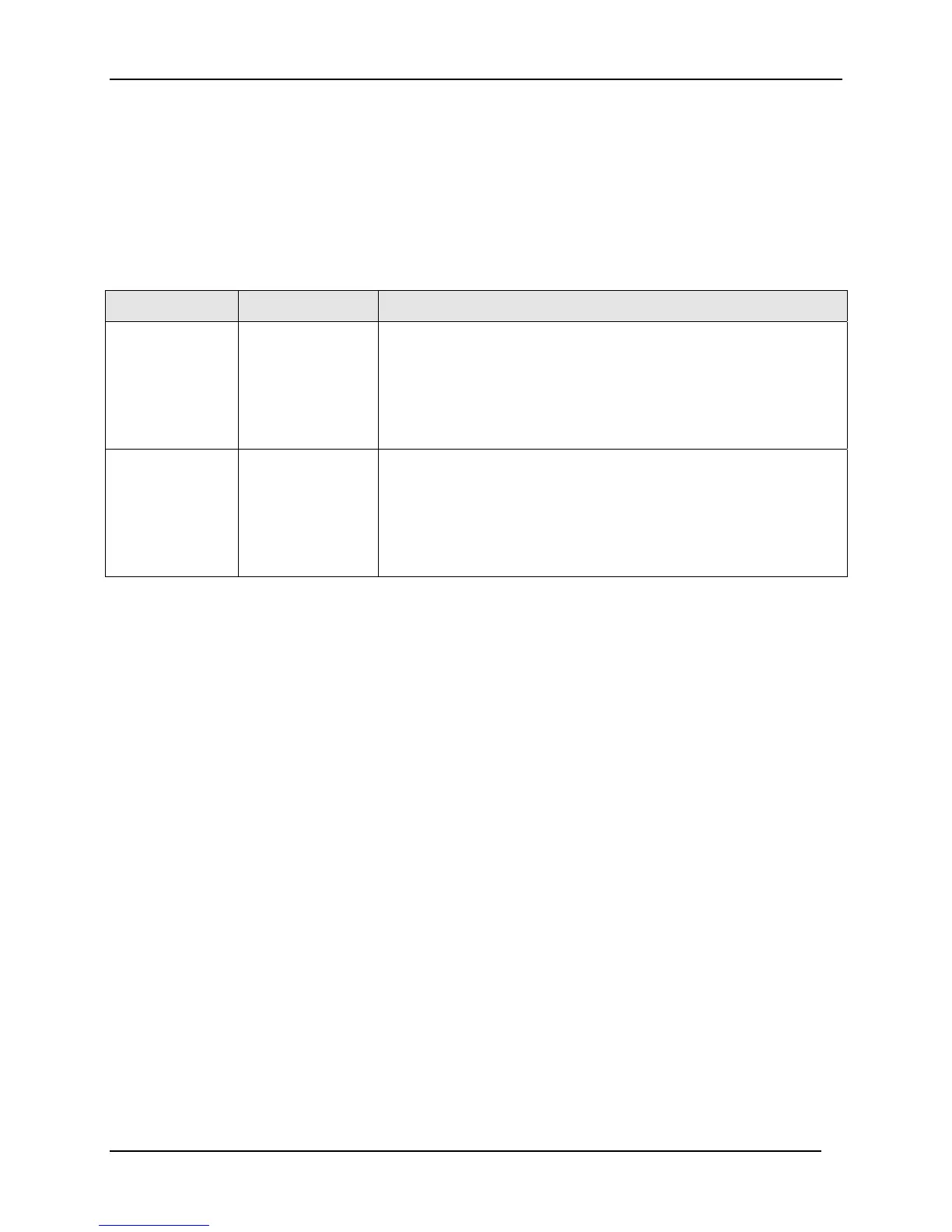
Table 4-24 Digital Display Indication—Two Loops
Indicator Loop Indication Definition
none
(two-loop)
I
(cascade)
Loop 1 • Upper display shows the Process Variable (PV) for Loop 1
• Lower display shows the Loop 1 parameters and the PV and
Output for Loop 2
• Controller setpoint annunciators show the setpoint currently
being used for Loop 1
L”
Loop 2 • Upper display shows the Process Variable (PV) for Loop 2
• Lower display shows the Loop 2 parameters and the PV and
Output for Loop 1
• Controller setpoint annunciators show the setpoint currently
being used for Loop 2
Loop Display
Display of Loop 1 or Loop 2 (if configured) is selected by toggling the Func-Loop1/2 key.
Viewing each Loop’s Process Variable
Regardless of which loop is being displayed, 1 or 2, the process variable of the non-
displayed loop can be shown in the lower display by repeated presses of the Lower
Display
key until 1PVXXXX or 2PVXXXX is displayed.
Internal Cascade Indication
When internal Cascade has been configured, an “I” will appear on the left side of the
upper display as long as Loop 1 is operating in the remote setpoint mode. Hold in the
SP Select key until RSP appears in the lower display then release the key to select remote
setpoint.
Switching between automatic and manual mode on either loop will not affect the internal
Cascade indication.

 Loading...


