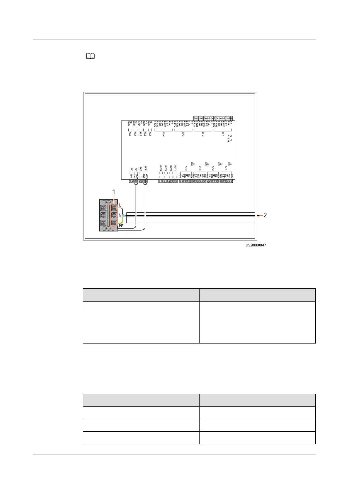
Pay attention to the polarity when connecting cables.
Figure 4-34 Connecting cables to the access controller
(1) Connecting the power cable for the access
controller
(2) Connecting to the power supply, as
described in Table 4-33
Table 4-33 Power cable connection for the access controller
Power Supply
Cable Connection
Power supply outside the equipment
room
Install the connector (BOM number:
14170096) to the other end of the
power cable and connect the power
cable to a circuit breaker in the power
supply outside the equipment room.
Related Information
Table 4-34 Card reader and key terminal denition
Terminal Identity
Denition
BT Key input
R-AL Card reader pry signal input
R-BP Control card reader buzzer
iMaster NetEco
Device Installation and Commissioning Guide (Data
Center) 4 Connecting Monitoring Cables to Devices
Issue 02 (2021-05-12) Copyright © Huawei Technologies Co., Ltd. 111
 Loading...