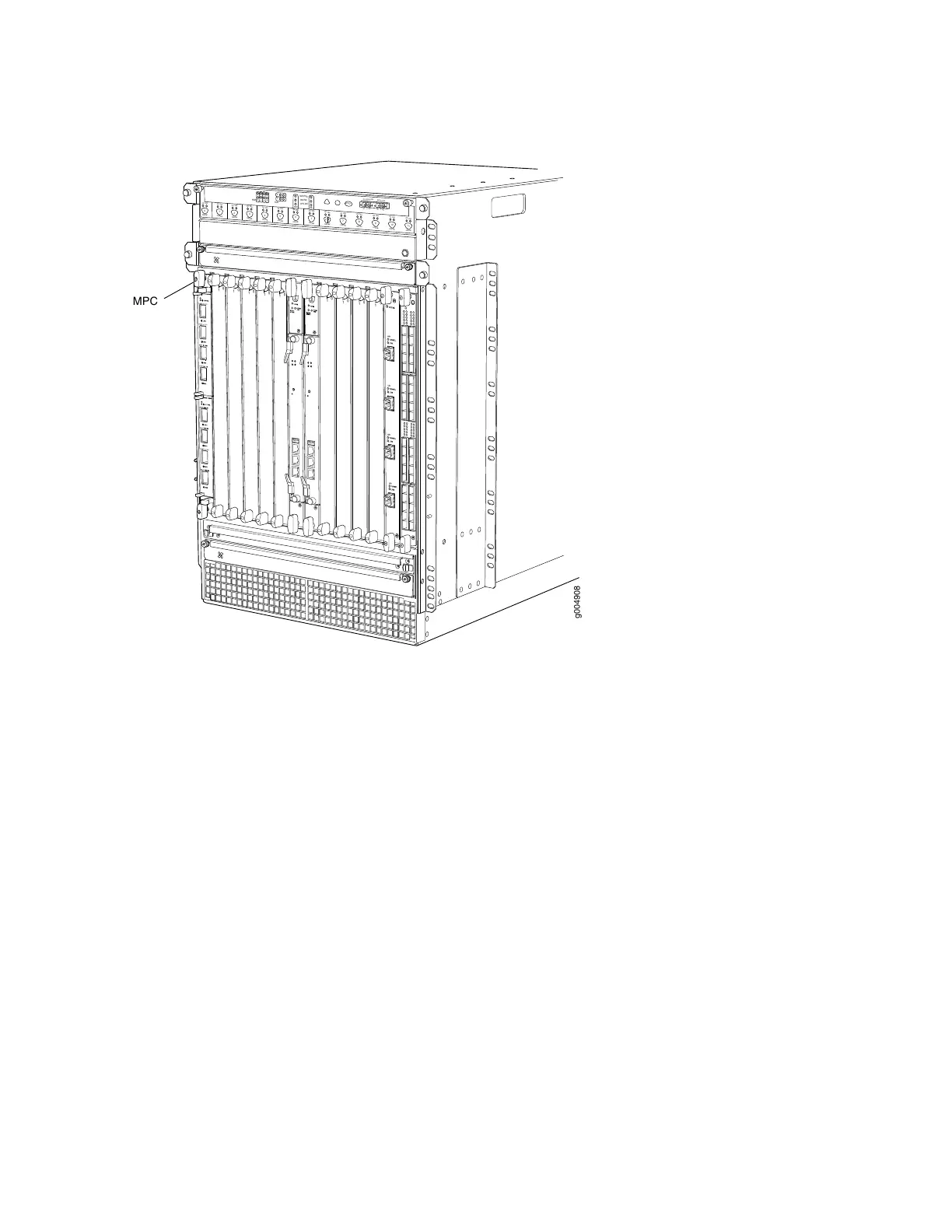
Figure 30: MPC Installed Vertically in the MX960 Router
OK
0
FAIL
ONLINE
OK
1
FAIL
ONLINE
OK
2
FAIL
ONLINE
OK
3
FAIL
ONLINE
OK
4
FAIL
ONLINE
OK
5
FAIL
ONLINE
OK
0
FAIL
ONLINE
MASTER
ONLINE
OFFLINE
RE0
FAN
PEM
1
0
0
1
2
3
RE1
OK
1
FAIL
ONLINE
OK
7
FAIL
ONLINE
OK
8
FAIL
ONLINE
OK
9
FAIL
ONLINE
OK
10
FAIL
ONLINE
OK
11
FAIL
ONLINE
OK
2
6
FAIL
ONLINE
ACO/LT
YELLOW ALARM
RED ALARM
NC
NO
C
NC
NO
C
1
0
1
0
1
0
1
0
1
0
1
1
0
0
1
0
1
0
g004908
MPC
MPC Components
Each MPC consists of the following components:
•
MPC card carrier, which includes two MIC slots (excludes the fixed configuration MPC).
•
Fabric interfaces.
•
Two Gigabit Ethernet interfaces that allow control information, route information, and statistics to be
sent between the Routing Engine and the CPU on the MPCs.
•
Two interfaces from the SCBs that enable the MPCs to be powered on and controlled.
•
Physical MPC connectors.
•
Up to four Junos Trio chipsets, which perform control functions tailored to the MPC’s media type.
•
Midplane connectors and power circuitry.
•
Processor subsystem, which includes a 1.5-GHz CPU, system controller, and 1 GB of SDRAM.
•
Online button which takes the MPC online or offline when pressed.
•
OK/Fail LED on the MPC faceplate. For more information about LEDs on the MPC faceplate, see the
MX Series Interface Module Reference.
115