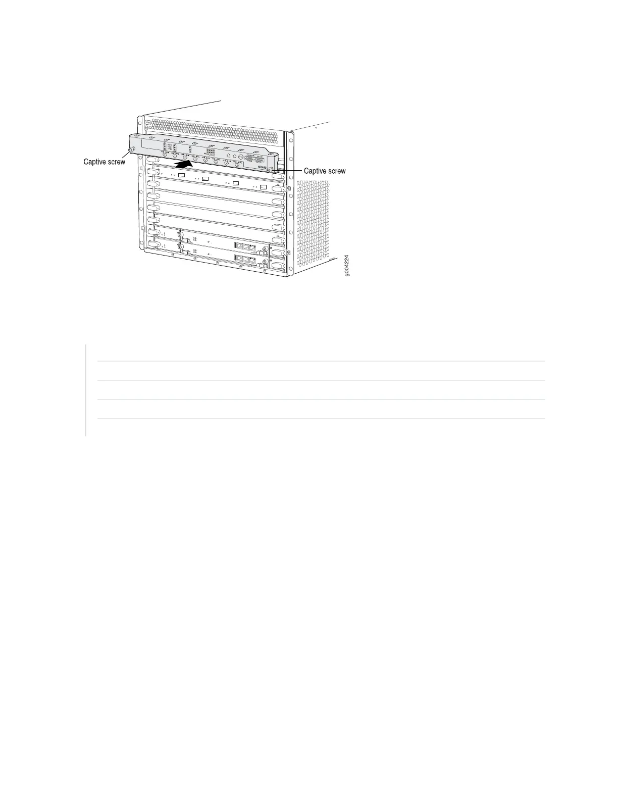
Figure 159: Installing the Craft Interface
SEE ALSO
Preventing Electrostatic Discharge Damage to an MX960 Router
Disconnecting the Alarm Relay Wires from the MX960 Craft Interface | 433
Removing the MX960 Craft Interface | 434
Connecting the Alarm Relay Wires to the MX960 Craft Interface | 367
MX960 Craft Interface Overview | 17
Connecting the Alarm Relay Wires to the MX960 Craft Interface
To connect the alarm relay wires between a router and an alarm-reporting device (see
Figure 132 on page 368):
1. Prepare the required length of replacement wire with gauge between 28-AWG and 14-AWG (0.08 and
2.08 mm
2
).
2. Insert the replacement wires into the slots in the front of the block. Use a 2.5-mm flat-blade screwdriver
to tighten the screws and secure the wire.
3. Wrap and fasten one end of the ESD grounding strap around your bare wrist, and connect the other
end of the strap to the ESD point on the chassis.
436