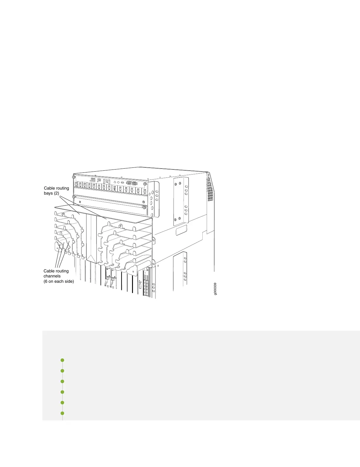
The extended cable manager contains two cable routing bays, and each bay contains six cable routing
channels (see Figure 74 on page 285, which shows the extended cable manager with its cover removed).
Each routing channel corresponds to a DPC below it. You route the cables from a DPC through the bottom
of a routing channel and out the side of the bay. The retaining flanges on each channel keep the cables
inside the channels.
The extended cable manager is used in conjunction with the standard cable manager attached to the
bottom of the chassis. We recommend that you use the standard cable manager for fiber-optic cables that
cannot fit in the extended cable manager and for cables that do not connect to a DPC (such as an
out-of-band Ethernet cable connected to the Routing Engine). See “Dressing the Cables” on page 317 for
more information about routing cables.
Figure 74: Extended Cable Manager With Cover Removed
g000339
3
4
Cable routing
bays (2)
Cable routing
channels
(6 on each side)
Installing the Extended Cable Manager
IN THIS SECTION
Powering Off the Router | 286
Removing the Craft Interface | 286
Removing the Upper Fan Tray | 287
Removing the AC Power Inlet Cover (DC-Powered Routers Only) | 288
Removing the Rear Air Exhaust Grate | 289
Disconnecting the Craft Interface Ribbon Cable from the Chassis Midplane | 295
285