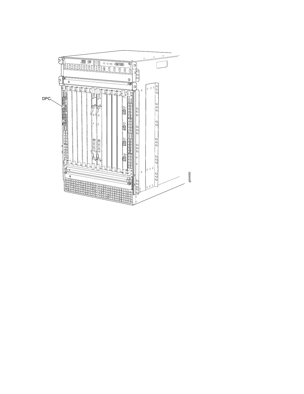
Figure 19: DPCs Installed Vertically in the MX960 Router
OK
0
FAIL
ONLINE
OK
1
FAIL
ONLINE
OK
2
FAIL
ONLINE
OK
3
FAIL
ONLINE
OK
4
FAIL
ONLINE
OK
5
FAIL
ONLINE
OK
0
FAIL
ONLINE
MASTER
ONLINE
OFFLINE
RE0
FAN
PEM
1
0
0
1
2
3
RE1
OK
1
FAIL
ONLINE
OK
7
FAIL
ONLINE
OK
8
FAIL
ONLINE
OK
9
FAIL
ONLINE
OK
10
FAIL
ONLINE
OK
11
FAIL
ONLINE
OK
2
6
FAIL
ONLINE
ACO/LT
YELLOW ALARM
RED ALARM
NC
NO
C
NC
NO
C
1
0
1
0
1
0
1
0
1
0
1
1
0
0
1
0
1
0
g004093
OK/
F
AIL
0/0
0/5
2/0
2/5
1/0
1/5
3/0
3/5
DPC
DPC Components
Each DPC consists of the following components:
•
DPC cover, which functions as a ground plane and a stiffener.
•
Fabric interfaces.
•
Two Gigabit Ethernet interfaces that allow control information, route information, and statistics to be
sent between the Routing Engine and the CPU on the DPCs.
•
Two interfaces from the SCBs that enable the DPCs to be powered on and controlled.
•
Physical DPC connectors.
•
Two or four Packet Forwarding Engines.
•
Midplane connectors and power circuitry.
•
Processor subsystem, which includes a 1.2-GHz CPU, system controller, and 1 GB of SDRAM.
•
Online button—Takes the DPC online or offline when pressed.
•
LEDs on the DPC faceplate. For more information about LEDs on the DPC faceplate, see the MX Series
Interface Module Reference.
65