Table 65: Zoning for High-Capacity Second-Generation Power Supplies in an MX960
Components Receiving Power
Power Supply
(PEM)ZoneChassis Power Configuration
•
Lower fan tray
DPC/MPC slots 6 through 11
•
SCB slots 1 through 2
PEM 0 or 2Zone 0High-capacity second-generation AC
power supplies
•
Upper fan tray
DPC/MPC slots 0 through 5
•
SCB slot 0
PEM 1 or 3Zone 1High-capacity second-generation AC
power supplies
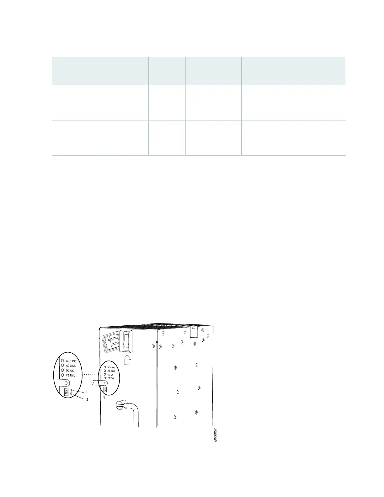
Understanding Input Mode Switch (DIP Switch) Settings
Each PSM has two input mode switches (DIP switches) on the faceplate. The DIP switches provide critical
information to the power management subsystem to help generate alarms in case of a feed failure or a
wrong connection. Each PSM has an LED per feed indicating whether the feed is active and whether the
feed is properly connected. You must set the DIP switch on each high-capacity AC or high-capacity
second-generation AC power supply according to how many feeds are connected. When one feed is
connected, the system is running in reduced capacity mode. When two feeds are connected the system
is running in full-capacity mode. Use these DIP switch settings:
•
Position-0 indicates one AC feed is present
•
Position-1 indicates two AC feeds are present
Refer to Figure 36 on page 136.
Figure 36: Setting the Input Mode Switch (DIP Switch)
136