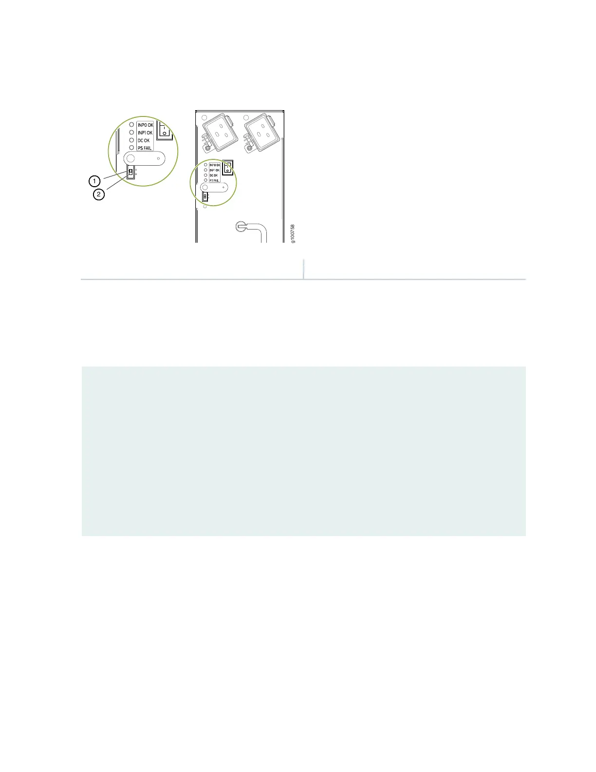
Figure 37: Setting the Input Mode Switch (DIP Switch) on High-Capacity Second-Generation AC PSM
2—1— Position 0 settingPosition 1 setting
Use the show chassis power command to verify that the DIP switch settings on the high-capacity AC
power supplies are set to the correct position. Here are examples of the command output:
Example 1: Proper setting of the DIP switch
user@host>show chassis power
PEM 0:
State: Online
AC input: OK (2 feed expected, 2 feed connected)
Capacity: 4100 W (maximum 4100 W)
DC output: 855 W (zone 0, 15 A at 57 V, 20% of capacity)
PEM 1:
State: Online
AC input: OK (1 feed expected, 1 feed connected)
Capacity: 1700 W (maximum 4100 W)
DC output: 969 W (zone 1, 17 A at 57 V, 57% of capacity)
In Example 1, PEM 0 is running at full capacity (4100 W) with two AC feeds expected and two AC feeds
connected. This indicates that the DIP switch is properly set to Position 1 since two AC feeds are connected.
The example also shows that PEM 1 is running at reduced capacity (1700W) with one AC feed expected
and one AC feed connected. This indicates that the DIP switch is correctly set to Position 0 since one feed
is present.
Example 2 shows the show chassis power command output when the DIP switch is set improperly:
137