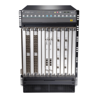
Powering On a DC-Powered MX960 Router with Normal Capacity Power
Supplies
1. Verify that an external management device is connected to one of the Routing Engine ports (AUX,
CONSOLE, or ETHERNET).
2. Turn on the power to the external management device.
3. Verify that the power supplies are fully inserted in the chassis.
4. Verify that the source power cables are connected to the appropriate terminal: the positive (+) source
cable to the return terminal (labeled RTN) and the negative (–) source cable to the input terminal (labeled
–48V).
5. Switch on the dedicated customer site circuit breakers to provide power to the DC power cables. Follow
your site’s procedures.
6. Check that the INPUT OK LED is lit steadily green to verify that power is present.
7. If power is not present:
•
Verify that the fuse is installed correctly, and turn on the breaker at the battery distribution fuse
board or fuse bay.
•
Check the voltage with a meter at the terminals of the power supply for correct voltage level and
polarity.
8. Wrap and fasten one end of the ESD grounding strap around your bare wrist, and connect the other
end of the strap to the ESD point on the chassis.
9. On each of the DC power supplies, switch the DC circuit breaker to the center position before moving
it to the on (|) position.
NOTE: The circuit breaker may bounce back to the off (O) position if you move the breaker
too quickly.
10. Verify that the BREAKER ON LED is lit green steadily.
11. Verify that the PWR OK LED is lit green steadily, indicating the power supply is correctly installed and
functioning normally.
350

 Loading...