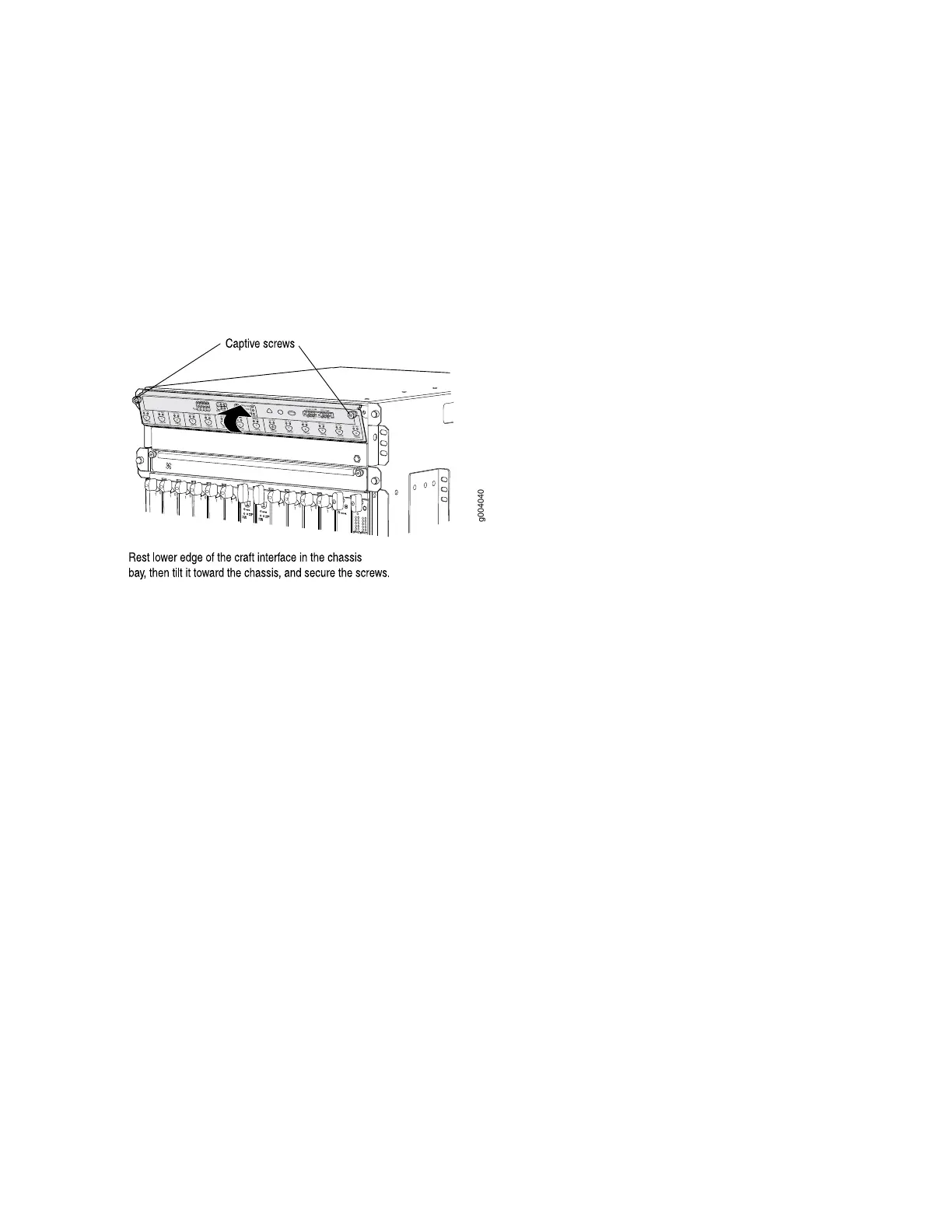
4. Align the bottom of the craft interface with the sheet metal above the DPC card cage and press it into
place.
5. Tighten the screws at the top left and right corners of the craft interface faceplate.
6. Reattach any external devices connected to the craft interface.
Figure 101: Installing a Craft Interface
1
0
1
0
1
0
1
0
1
0
1
1
0
0
1
0
1
0
1
0
g004040
OK
0
F
AIL
ONLINE
OK
1
F
AIL
ONLINE
OK
2
F
AIL
ONLINE
OK
3
F
AIL
ONLINE
OK
4
F
AIL
ONLINE
OK
5
F
AIL
ONLINE
OK
0
F
AIL
ONLINE
MASTER
ONLINE
OFFLINE
RE0
F
AN
PEM
1
0
0
1
2
3
RE1
OK
1
F
AIL
ONLINE
OK
7
F
AIL
ONLINE
OK
8
F
AIL
ONLINE
OK
9
F
AIL
ONLINE
OK
10
F
AIL
ONLINE
OK
1
1
F
AIL
ONLINE
OK
2
6
F
AIL
ONLINE
ACO/L
T
YELLO
W ALARM
RED ALARM
NC
NO
C
NC
NO
C
Powering On the Router
To power on the router, follow this procedure:
1. Attach an electrostatic discharge (ESD) grounding strap to your bare wrist, and connect the strap to
one of the ESD points on the chassis.
2. Verify that the power supplies are fully inserted in the chassis and that each of their release levers is
locked into the chassis in the rightmost position.
3. For each power supply on an AC-powered router, verify that the source power cord is securely inserted
into the appliance inlet. For each power supply on a DC-powered router, verify that the source power
cables are connected to the appropriate terminal: the positive (+) source cable to the return terminal
(labeled RETURN) and the negative (–) source cable to the input terminal (labeled –48V).
4. Verify that an external management device is connected to one of the Routing Engine ports on the
Craft Interface (AUX, CONSOLE, or ETHERNET). For more information on connecting management
devices, see the MX960 3D Universal Edge Router Hardware Guide.
5. Turn on the power to the external management device.
315