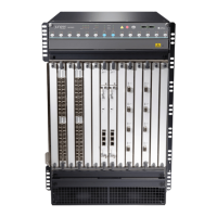
Removing Components from the MX960 Router Chassis Before Installing
It with a Lift
Before installing the router with a lift, you must first remove components from the chassis, and reinstall
the components the router is installed in the rack. With components removed, the chassis weighs
approximately 150 lb (68.04 kg).
1.
Removing the Power Supplies Before Installing an MX960 Router with a Lift | 265
2.
Removing the Standard Cable Manager Before Installing an MX960 Router with a Lift | 268
3.
Removing the Fan Trays Before Installing an MX960 Router with a Lift | 269
4.
Removing the SCBs Before Installing an MX960 Router with a Lift | 271
5.
Removing the DPCs Before Installing an MX960 Router with a Lift | 272
6.
Removing the FPCs Before Installing the MX960 Router with a Lift | 274
Removing the Power Supplies Before Installing an MX960 Router with a Lift
Remove the leftmost power supply first and then work your way to the right. To remove the AC, DC, or
universal power supplies (see Figure 59 on page 266, Figure 60 on page 267, and Figure 61 on page 268):
1. Attach an electrostatic discharge (ESD) grounding strap to your bare wrist, and connect the strap to
an approved site ESD grounding point. See the instructions for your site.
2. On an AC-powered router, move the AC input switch in the chassis above each power supply to the
off (O) position. On a DC-powered router, move the DC circuit breaker on each power supply faceplate
to the off (O) position.
We recommend this even though the power supplies are not connected to power sources.
3. While grasping the handle on the power supply faceplate with one hand, use your other hand to pull
the spring-loaded locking pin in the release lever away from the chassis and turn the release lever
counterclockwise until it stops.
4. Let go of the locking pin in the release lever. Ensure that the pin is seated inside the corresponding
hole in the chassis.
5. Pull the power supply straight out of the chassis.
WARNING: Do not touch the power connector on the top of the power supply.
It can contain dangerous voltages.
265

 Loading...