42 JVL Industri Elektronik A/S - User Manual - Integrated Stepper Motors MIS23x, 34x, 43x
2.11 How to connect MIS34x
2.11.6 MIS34xxxxExxxxx connector description.
Hardware wise all the MIS34x motors with the Ethernet option are equal and offer the
connectivity shown in the table below.
The following Ethernet protocols are supported in this moment:
MIS34xxxxEPxxxx : ProfiNet
MIS34xxxxEIxxxx : EtherNetIP
MIS34xxxxECxxxx : EtherCAT
MIS34xxxxELxxxx : Ethernet POWERLINK
MIS34xxxxEMxxxx : Modbus TCP
Following Ethernet protocols are supported in the near future:
MIS34xxxxESxxxx : Sercos III
he MIS34x offers robust M12 connectors which makes it ideal for automation applica-
tions. The M12 connectors offer solid mechanical protection and are easy operate.
Following scheme gives the relevant information about each connector and the pins, wire
colours and a short description of the signals available.
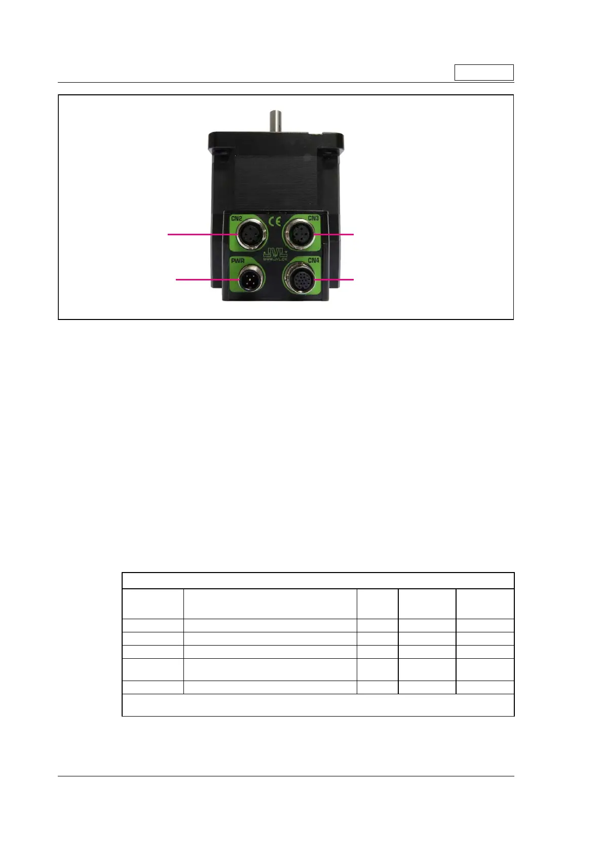
The connector layout:
(Continued next page)
“PWR” (CN1) - Power input. M12 - 5pin male connector
Signal name Description Pin no.
JVL Cable
WI1000-
M12F5TxxN
Isolation
group
P+ Main supply +12-80VDC. Connect with pin 2 * 1 Brown 1
P+ Main supply +12-80VDC. Connect with pin 1 * 2 White 1
P- Main supply ground. Connect with pin 5 * 3 Blue 1
CVI
Control and user output supply +12-30VDC.
DO NOT connect >30V to this terminal !
4 Black 1
P- Main supply ground. Connect with pin 3 * 5 Grey 1
* Note: P+ and P- are each available at 2 terminals. Make sure that both terminals are connected in order
to split the supply current in 2 terminals and thereby avoid an overload of the connector.
Only MIS34x
TT2335-01GB.cdr
PWR (CN1)
Power input
CN2
Ethernet In
CN3
Ethernet Out
CN4
RS485 + I/O + Backup(optional)

 Loading...