46 JVL Industri Elektronik A/S - User Manual - Integrated Stepper Motors MIS23x, 34x, 43x
2.11 How to connect MIS34x
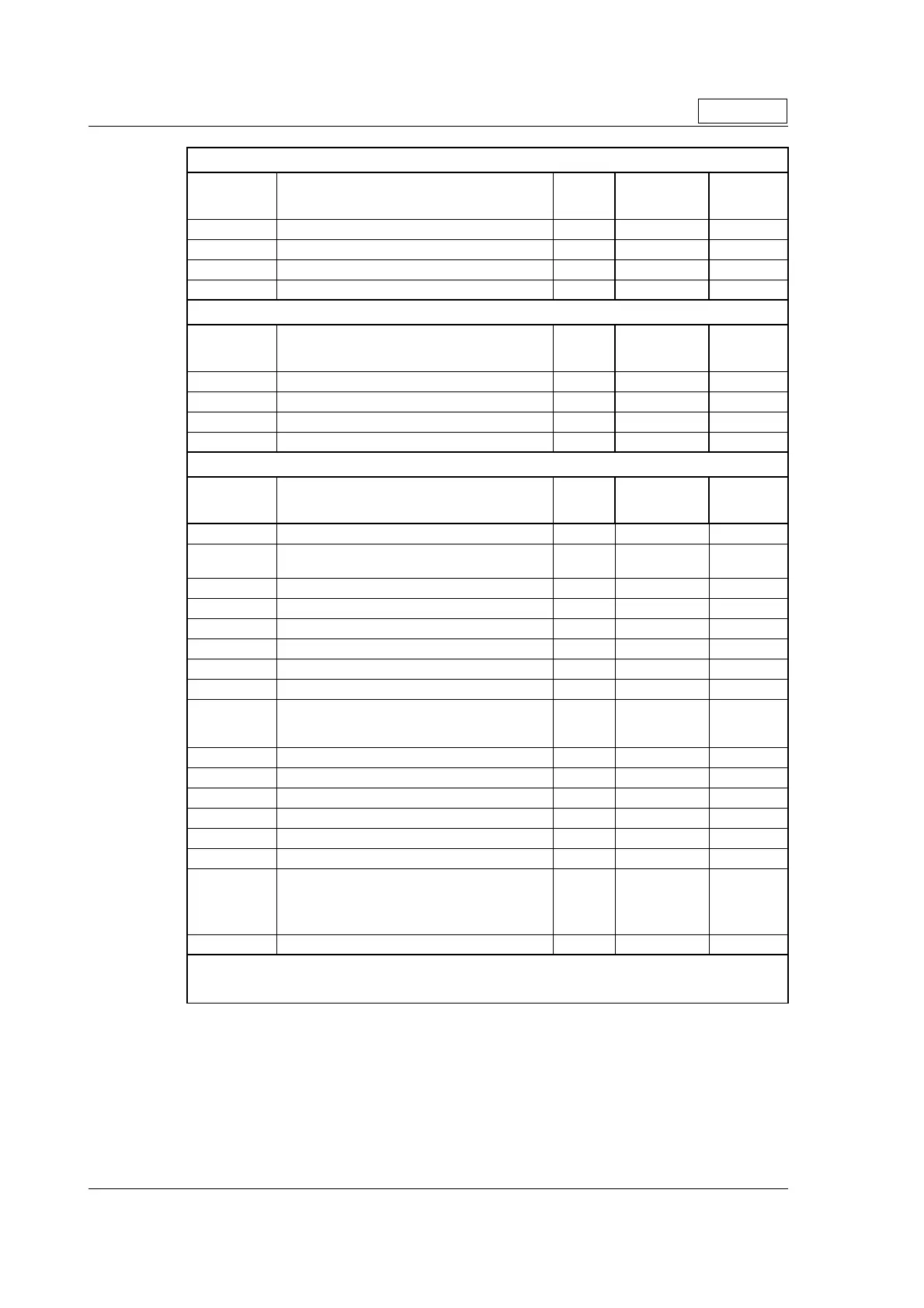
“CN2” - Ethernet In port connector - M12 - 4pin female connector “D” coded
Signal
name Description Pin no.
JVL Cable
WI1046-
M12M4S05R
Isolation
group
(See note)
Tx0_P Ethernet Transmit channel 0 - positive terminal 1 - 2
Rx0_P Ethernet Receive channel 0 - positive terminal 2 - 2
Tx0_N Ethernet Transmit channel 0 - negative terminal 3 - 2
Rx0_N Ethernet Receive channel 0 - negative terminal 4 - 2
“CN3” - Ethernet Out port connector. M12 - 4 pin female connector “D” coded
Signal
name Description Pin no.
JVL Cable
WI1046-
M12M4S05R
Isolation
group
(see note)
Tx1_P Ethernet Transmit channel 1 - positive terminal 1 - 3
Rx1_P Ethernet Receive channel 1 - positive terminal 2 - 3
Tx1_N Ethernet Transmit channel 1 - negative terminal 3 - 3
Rx1_N Ethernet Receive channel 1 - negative terminal 4 - 3
“CN4” - RS485 + I/O + Backup (option) connector - M12 - 17pin female connector
Signal
name Description Pin no.
JVL Cable
WI1009M12
M17TxxN
Isolation
group
(see note)
IO1 I/O channel 1. Can be used as input or output 1 Brown 1
GND
Ground intended to be used together with the
other signals in this connector
2 Blue 1
IO2 I/O channel 2. Can be used as input or output 3 White 1
IO3 I/O channel 3. Can be used as input or output 4 Green 1
B1- RS422 I/O terminal B- 5 Pink 1
IO4 I/O channel 4. Can be used as input or output 6 Yellow 1
A1- RS422 I/O terminal A- 7 Black 1
B1+ RS422 I/O terminal B+ 8 Grey 1
CVO Supply output. Connected internally to the CVI
terminal in the PWR connector.
DO NOT connect >30V to this terminal !
9 Red 1
A1+ RS422 I/O terminal A+ 10 Violet 1
IO5 I/O channel 5. Can be used as input or output 11 Grey/Pink 1
IO6 I/O channel 6. Can be used as input or output 12 Red/Blue 1
IO7 I/O channel 7. Can be used as input or output 13 White/Green 1
IO8 I/O channel 8. Can be used as input or output 14 Brown/Green 1
RS485: B+ RS485 interface. Leave open if unused 15 White/Yellow 1
GND/
EXTBACKUP
Only for motors installed with the H3 option (ab-
solute multi turn encoder).
This terminal can be connected to an external
supply. Connect to ground if not used.
16
Yellow/Brown
1
RS485: A- RS485 interface. Leave open if unused 17 White/Grey 1
* Note: Isolation group indicate which terminals/circuits that a galvanic connected to each other. In other
words group 1, 2, 3 and 4 are all fully independently isolated from each other. Group 1 correspond to the
housing of the motor which may also be connected to earth via the DC or AC input supply.
Only MIS34x

 Loading...