1-2
Version 1.73 Copyright © 1997 Link Communications Inc. 1/18/97
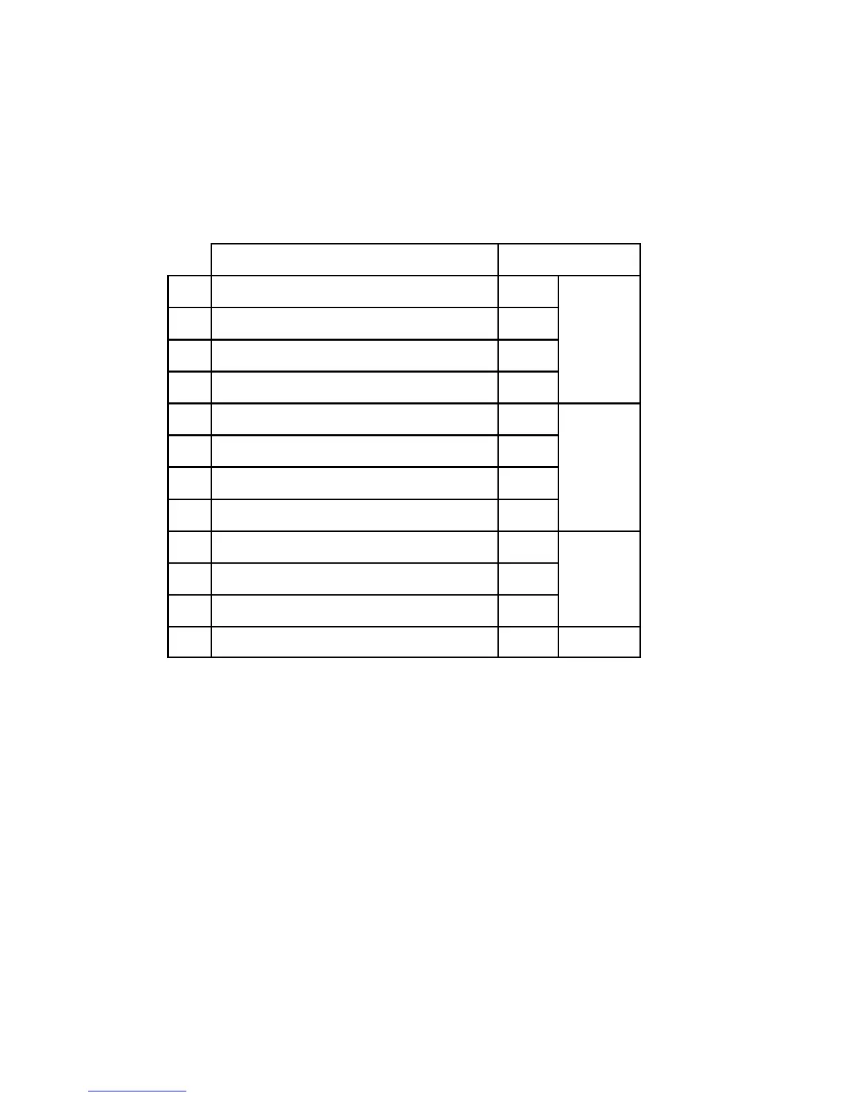
What the LED's Represent:
The RLC-Club has 12 LED's to help you get it set up and to let you how how the repeater is
being used. If you purchased the rack mount cabinet, there will be labels by the LED's to help
you remember what each one means. The below table lists the descriptions for the LED's and
the label that is on the rack cabinet.
Description Front Panel Label
1 Port 1 COR Active C Port 1
2 Port 1 PL Active P
3 Port 1 Transmitter (PTT) Active T
4 Port 1 DTMF Detected D
5 Port 2 COR Active C Port 2
6 Port 2 PL Active P
7 Port 2 Transmitter (PTT) Active T
8 Port 2 DTMF Detected D
9 Autopatch Ringing R Patch
10 Autopatch Off Hook H
11 Autopatch DTMF Detected D
12 DVR Active (playing or recording) A DVR
Step #2: Connect Power
- The RLC-Club was designed to run off of 12V DC. 11V to 14V should work fine.
- Locate the 2.50mm power connector included in your parts bag.
- Unscrew the plastic outer shield and thread your power and ground wires through it (20 gauge
suggested).
- Solder the +12V wire to the center pin of the 2.50mm connector.
- Solder the ground wire to the shield of the 2.50mm power connector.
- Screw on the plastic outer shield.
- When power is applied to the RLC-Club controller, some of the front panel LED's will light
indicating a PTT condition. If none of the LED's light, turn off the power immediately .
 Loading...