H-1
Version 1.73 Copyright © 1997 Link Communications Inc. 1/18/97
Appendix H: Using the LM335 Temperature Sensor
The RLC-Club supports the National Semiconductor LM335Z temperature sensor. The sensor
converts temperature into voltage. This voltage is read by the controllers ADC (Analog-Digital
Convertor) which allows the controller to read a voltage. When using the LM335Z sensor, the
sensor needs to be powered in order for the temperature to be read. Powering the sensor is
accomplished by connecting the sensor to Analog inputs 1 or 2 or 3 .
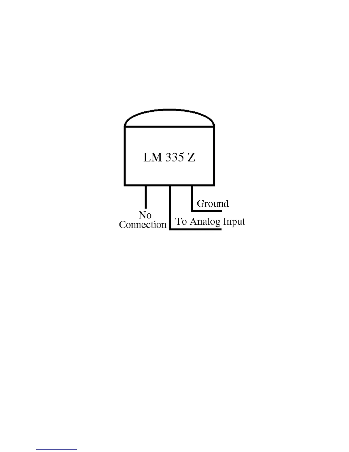
LM335Z Temperature Probe Connections Diagram
- If you have your temperature sensor hooked up backwards (+OUT switched with the -GND)
you will read ~0.6 volts across the sensor.
- Verify the sensor is connected to an Analog input that has a powering resistor associated with
the input. Analog 1,2,3 connector P4 pins 1,2,3 contain the powering resistor.
- Voltage meter reading at the sensor measure: Temperature Celsius = (voltage*100)-273
 Loading...