J-1
Version 1.73 Copyright © 1997 Link Communications Inc. 1/18/97
Appendix J: Hardware Reference Section
Important Connections:
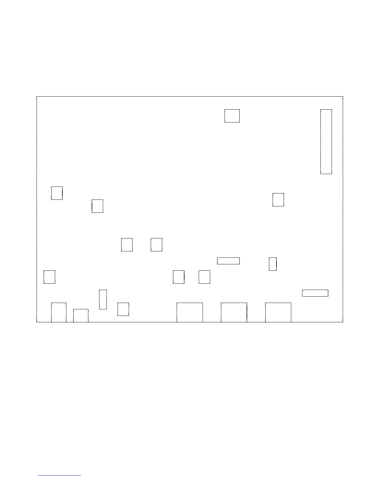
RLC-Club Main Board
DELUXE
INITIALIZATION MODULE
SWITCH CONNECTION
VOICE LEVEL
ADJUSTMENT
RESET SWITCH
AUTOPATCH
AUDIO INPUT
ADJUSTMENT
AUTOPATCH AUTOPATCH RLC-ADM
AUDIO OUTPUT DTMF LEVEL AUDIO DELAY
ADJUSTMENT ADJUSTMENT MODULE
-6dB
RECEIVER
AUTOPATCH TRANSMIT RECEIVER FILTER
EARTH GROUND ADJUSTMENT ADJUSTMENT
CONNECTION
500mA RS-232 ANALOG RADIO
PHONE LINE FUSE SERIAL INPUTS PORT 1
+12V TONE LEVEL RLC-MOT
ADJUSTMENT SQUELCH
MODULE
Adjustments:
Voice level adjustment allows you to vary the level of the voice synthesis generator. Adjust this level to
2 Khz. deviation. Refer to Chapter 1 for level adjustments.
Connections:
There are 3 supported options on the RLC-Club main board. These include the 'RLC-MOT' squelch
module, 'RLC-ADM' digital audio delay module and the RLC-Club Deluxe module interface.
Initialize and Reset switches:
These switches are provided to allows the manual resetting and initialization of the controller. See
Appendix D for instructions about how to perform the initialization.
 Loading...