ASSEMBLING THE W INDROWER
13. Install pin (B) through the header leg (engaging
U-bracket in lift linkage) on both sides and secure with
hairpin ( A).
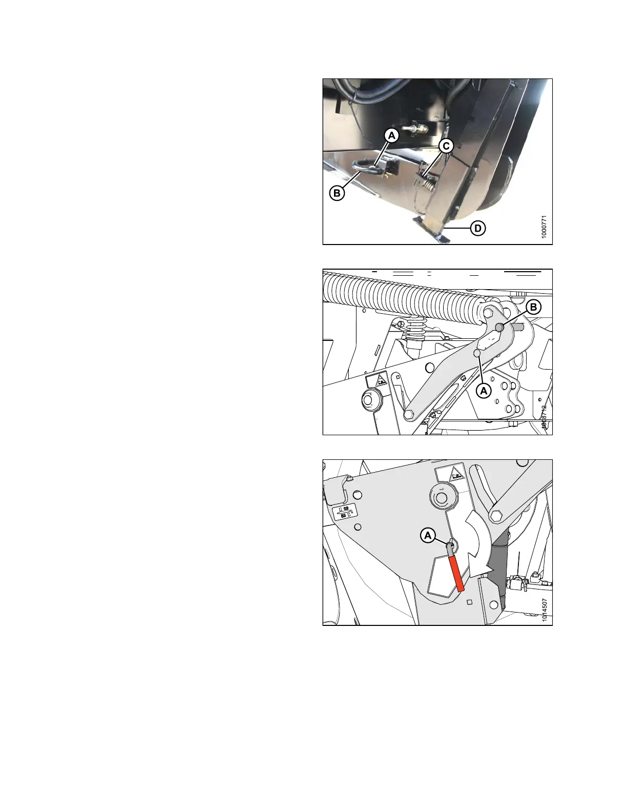
14. Raise header stan d (D) to storage po sition by pulling
spring pin (C) and lifting stand into uppermost position.
Release spring pin.
Figure 3.183: Header Leg
15. Remove cle vis pin from storage po sition (B) in link ag e
and insert into hole (A) to eng age float springs. Sec ure
with hairpin.
Figure 3.184: Header Float Linkage
16. Disengage safety prop by turning lever (A) downwards
to release and lower stop until lever locks into
vertical position.
17. Repeat for opposite safety prop.
Figure 3.185: Safety Prop
147962 108 Revision A
 Loading...


