ASSEMBLING THE W INDROWER
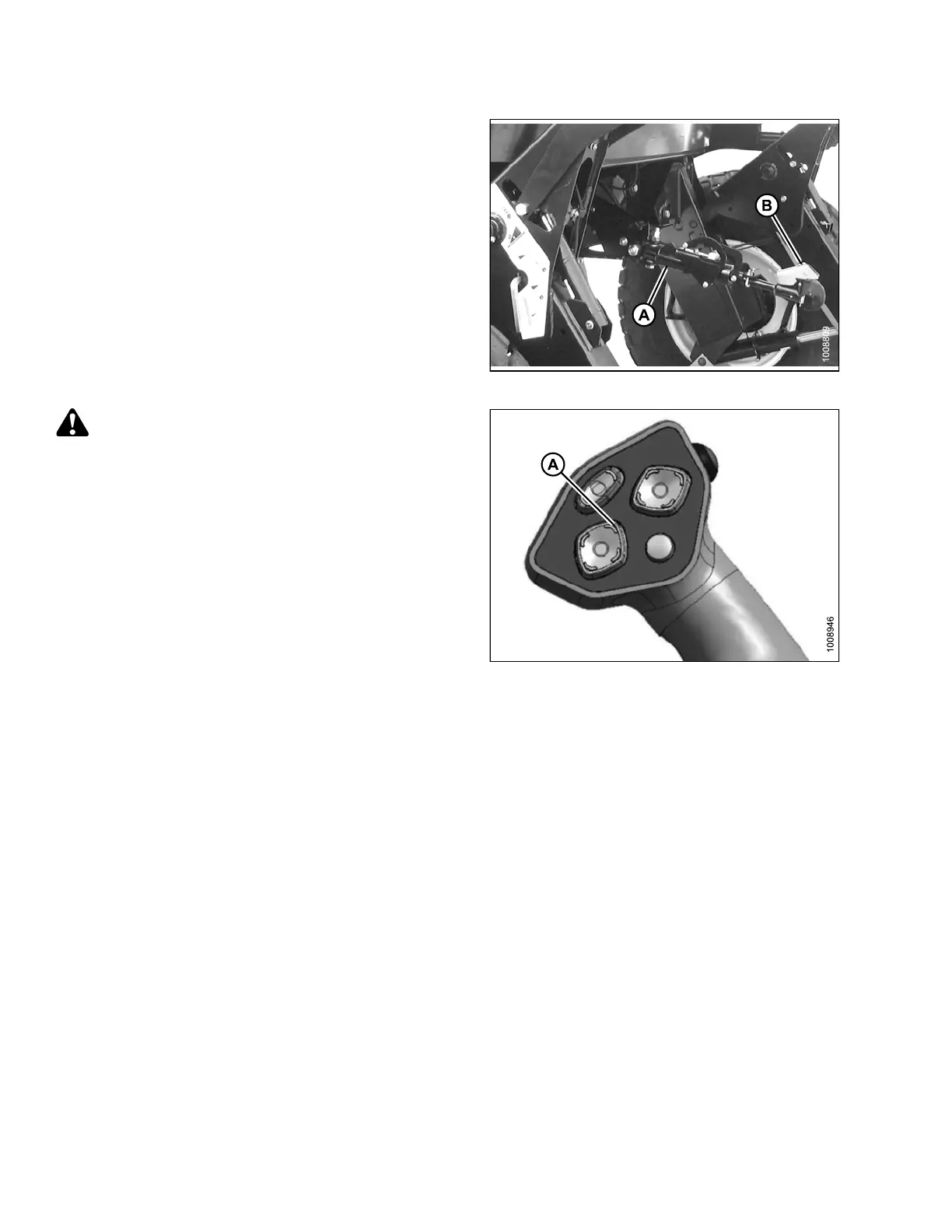
6. Adjust position o f the center-lin k cylinder ( A) with
the REEL UP and REEL DOWN switches on the
GSL until the hook is positioned above the header
attachment pin.
IMPORTANT:
Hook release must be down to enable self-locking
mechanism. If the release is open (up), manually
push it down after hook engages header pin.
7. Lower center-link (A) onto the header with REEL
DOWN switch until it locks into position (hook
release [B] is down).
8. Check that center-link is locked onto header by
pressing the REEL UP switch on the GSL.
Figure 3.210: Hydraulic Center-Link
CAUTION
Check to be sure a ll bystanders have cleared t he area.
9. Press the HEADER UP switch (A) to raise header to
maximum height.
NOTE:
If one end of the header does NOT fully rise, rephase
the lift cylinders as follows:
a. Press and hold the HEADER UP switch until both
cylinders stop moving.
b. Cont inue to ho ld the switch for 3–4 seconds.
Cylinders are now phased.
NOTE:
It may be necessary to repeat this procedure if
there is air in the system.
Figure 3.211: G round Speed Lever
147962 118 Revision A
 Loading...


