ASSEMBLING THE WINDROWER
4. Drive the windrower slowly forward until the win drower
feet (A) enter the header boots (B). Continue driving
slowly forward until the feet engage the boots and the
header nudges forward.
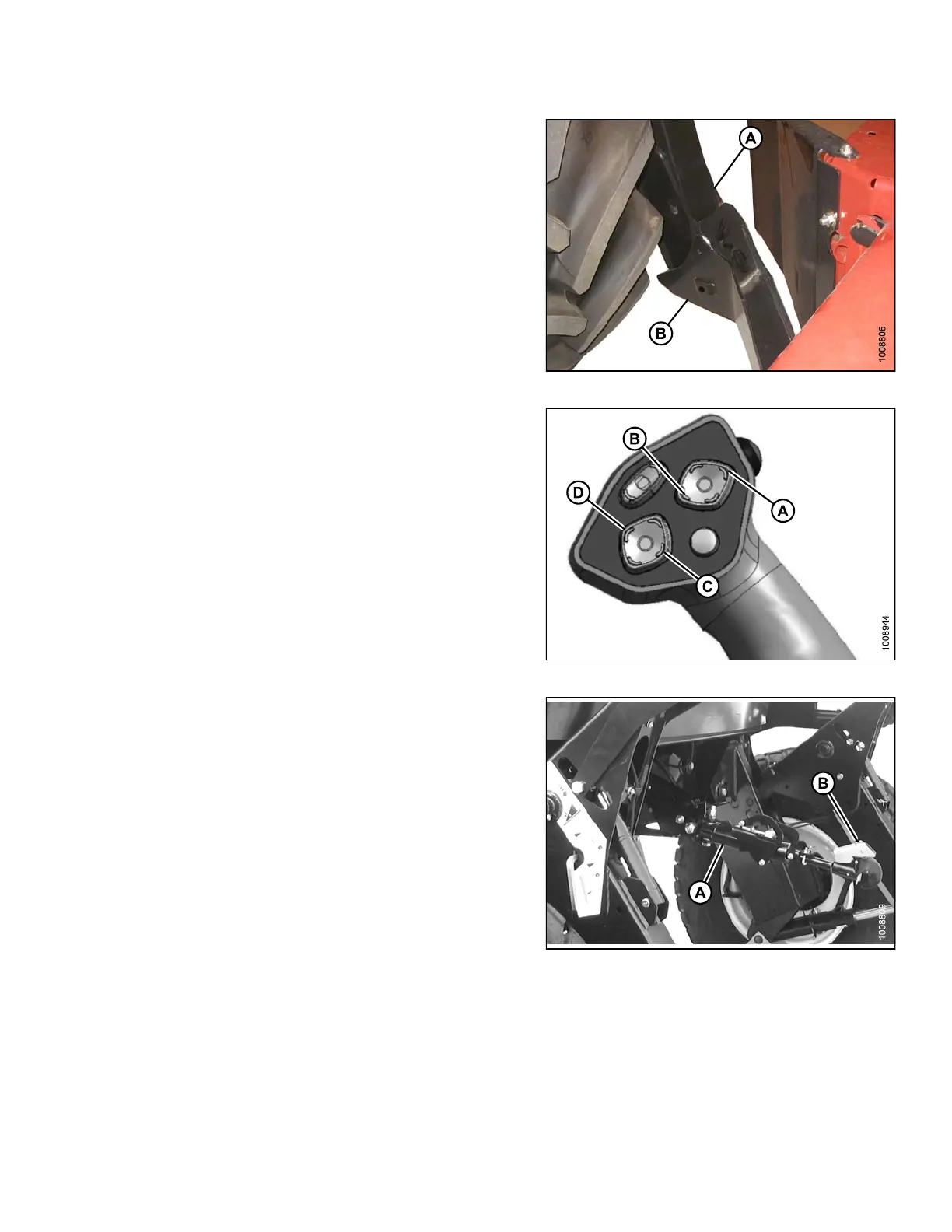
Figure 3.253: Header Boot
5. Use the following GSL functions to position the
center-link hook above the header attachment pin:
• Reel u p (A) to raise the center-link
• Reel down (B) to lower the center-link
• Header tilt up (C) to retract the center-link
• Header tilt down (D) to extend the center-link
Figure 3.254: Ground Speed Lever
6. Adjust position of the center-link cylinder (A) with
the REEL UP and REEL DOWN switches on the
GSL until the hook is positioned above the header
attachment pin.
IMPORTAN T:
Hook release must be down to enable self-locking
mechanism. If the release is open (up), manually
push it down after hook engages header pin.
7. Lower center-link (A) onto the header with REEL
DOWN switch until it locks into position (hook
release [B] is dow n).
8. Check that center-link is locked o nto header by
pressingtheREELUPswitchontheGSL.
Figure 3.255: Hydraulic Center-Link
147962 135 Revision A