ASSEMBLING THE W INDROWER
4. Stop engine and remove key from ignition.
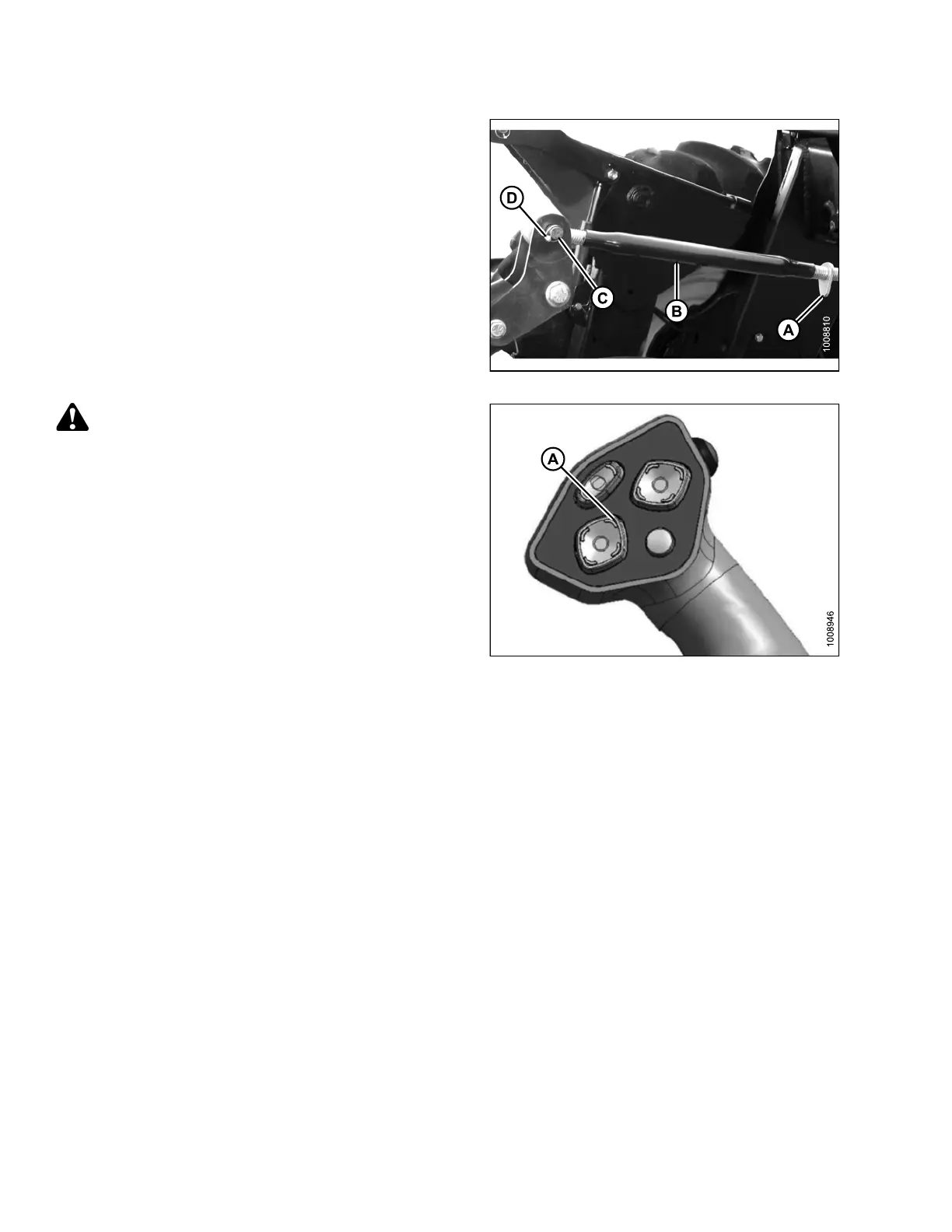
5. Loosen nut (A) and rotate barrel (B) to adjust length
until the link is aligned with the header bracket.
6. Install clevis pin (C) and secure with cotter pin (D).
7. Adjust length of link to achieve proper header angle
by rotating barrel (B). Tighten nut (A) against barrel (a
slight tap with a hamme r is sufficient).
Figure 3.283: Mechanical Center-Link
CAUTION
Check to be sure a ll bystanders have cleared t he area.
8. Start the engine.
9. Press the HEADER UP switch (A) to raise header to
maximum height.
NOTE:
If one end of the header does NOT fully rise, rephase
the lift cylinders as follows:
a. Press and hold the HEADER UP switch until both
cylinders stop moving.
b. Cont inue to ho ld the switch for 3–4 seconds.
Cylinders are now phased.
NOTE:
It may be necessary to repeat this procedure if
there is air in the system.
Figure 3.284: Ground Speed Lever
147962 146 Revision A