CAB DISPLAY MODULE (CDM)
CAUTION
Check to be sure all bystanders have cleared the area.
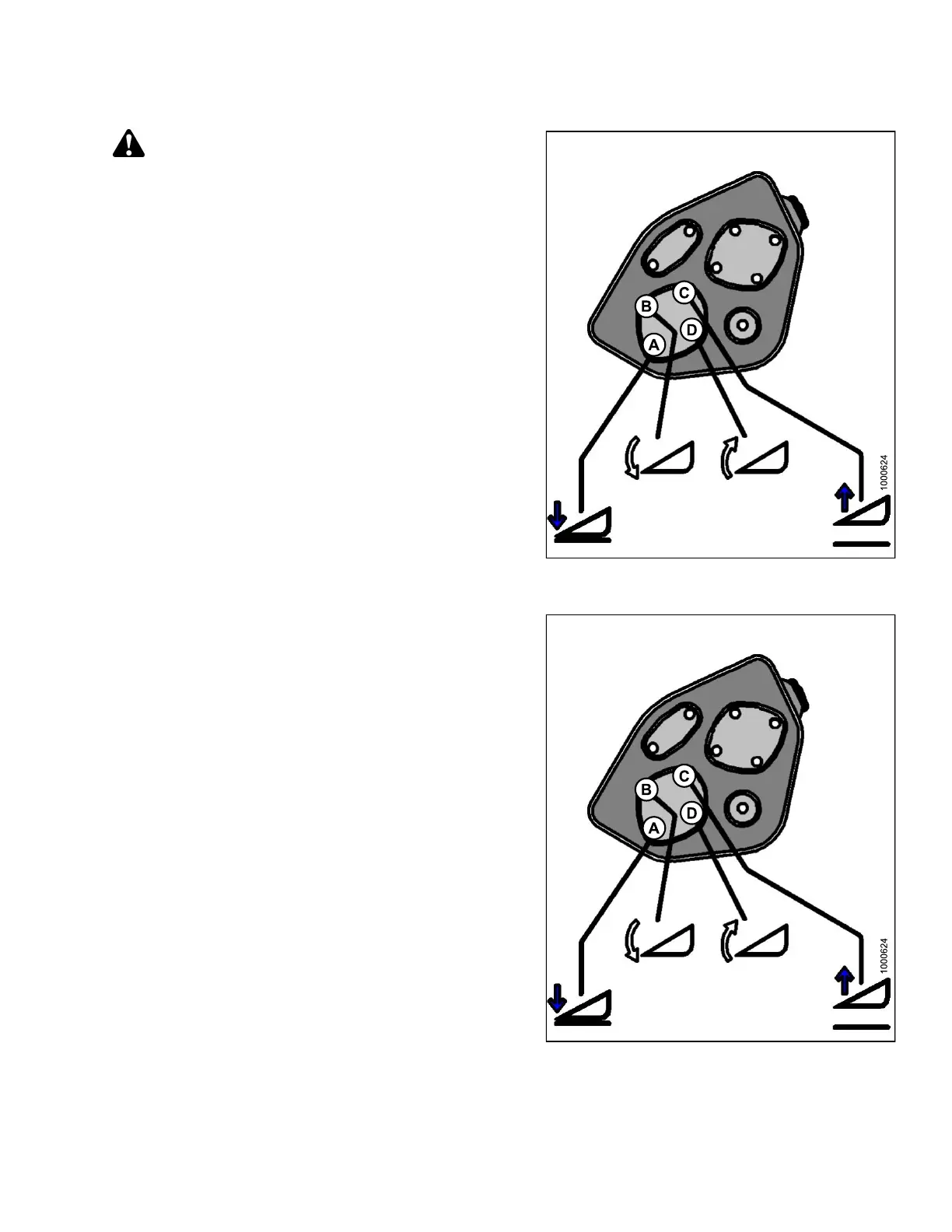
6. Press and hold the HEADER TILT EXTEND (B) button
on the ground speed lever (GSL).
• CALIBRATING TILT is displayed on the upper line.
• EXTEND TILT HOLD is displayed on the lower line.
NOTE:
ThewordHOLDwillflash during calibration.
HEADER TILT DONE will disp la y on the lower
line once calibratio n is complete.
7. Release the HEADER TILT EXTEND (B) button.
• HEADER TILT SENSOR CAL is displayed on
upper line.
• PRESS RETRACT TILT is displayed on the
lower lin e.
Figure 4.62: Header Tilt Controls on Ground
Speed Lever
8. Press and hold HEADER TILT RETRACT (D) button
on GSL.
• CALIBRATING TILT is displayed on the upper line.
• RETRACT TILT HOLD is displayed on the
lower lin e.
NOTE:
ThewordHOLDwillflash during calibration.
HEADER TILT COMPLETE will display on the
lower line once calibration is complete.
9. Release HEADER TILT RE TRACT (D) button.
• TO CALIBR ATE SELECT is displayed on the
upper line.
• HEADER TILT is display ed on the lower line.
10. Press right arrow to select next header sensor
calibration or STOP & EXIT. Press SELECT.
Refer to 4.3.1 Calibrating the Header Height Sensor,
page 172 or 4.3.3 Calibrating the Header Float
Sensors, page 180.
11. Press PROGRAM to exit Programming Mode.
Fi
gure 4.63: Header Tilt Controls on Ground
Sp
eed Lever
147962 179 Revision A