CAB DISPLAY MODULE (CDM)
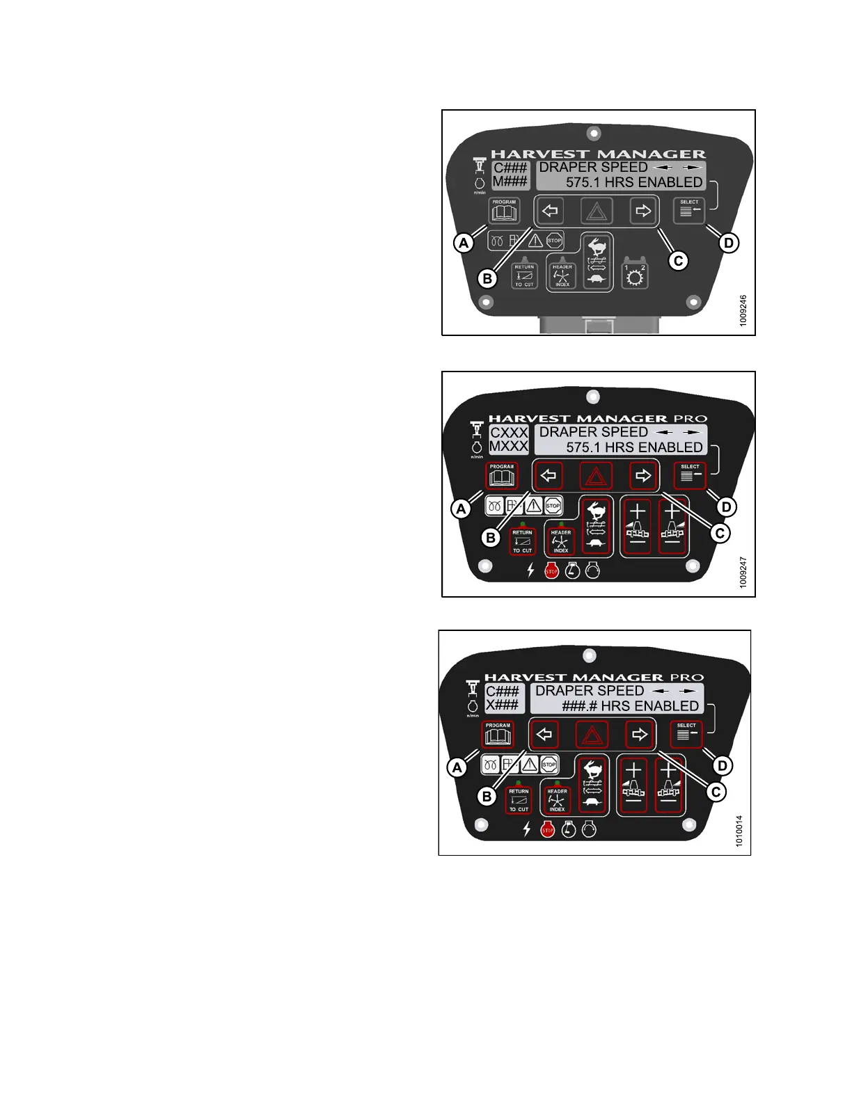
6. Press left (B) or right (C) arrow to cycle between control
switch lock outs. The disp layed control switches are
as follows :
•HEADERTILT
•HEADERFLOAT
• REEL FORE/AFT
• DRAPER SPEED
• AUGER SPEED
• KNIFE SPEED
• DISK SPEED
• REEL SPEED
NOTE:
Not all control locks apply to every header.
7. Press SE LECT.
• EXIT VIEW LOCKOUTS? is displayed on the
upper line.
• NO/YES is displayed on the lower line.
8. Press right to select YES.
9. Press PROGRAM to exit Programming Mode or
press SELEC T to proceed to ne xt WINDROWE R
SETUP action.
Figure 4.2
27: M105 Control Locks
Figur
e 4.228: M155 Control Locks
Figure 4.229: M205 Control Locks
147962 252 Revision A