ASSEMBLING THE W INDROWER
2. Position hose (MD #111323 [orange tie]) (D) and
hose (MD #111324 [white tie]) (E) with tee under the
center of the clip as shown, and loosely install two
bolts and nuts.
NOTE:
Part numbers
are marked on the hoses.
3. Position rem
aining hoses under clip as shown and
tighten bolt
s.
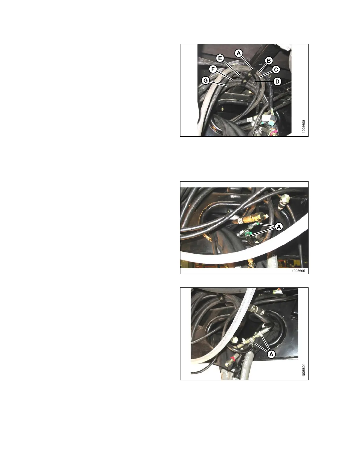
Figure 3.37: Hose Routing (View Looking
Forward)
A - Hose Clip B - Yellow Tie (MD #111557)
C-BlueTie
(MD #111323)
D-OrangeT
ie (MD #111323)
E - White Tie (MD #111324) F - Green Ti e (MD #111327)
G-WhiteTi
e (MD #111328)
4. Locate two h oses (MD #111327 [green ties] ) (A) in
frame opening and existing tee fitting (green tie) on the
hose from the valve block.
5. Remove caps from the hoses (A) only.
6. Remove on e cap from tee fitting, and quickly attach
hose (A) to minimize oil spillage.
7. Remove second c ap f rom tee fitting, and quickly
connect other hose (A).
8. Tighten fittings.
9. Position hoses into frame .
Figure 3.38: Hose Routing
10. Locate two hoses (white ties) inside frame and
hose (MD #111324) with e xisting tee fitting
(white tie ) (A).
11. Remove caps, make connections, and tighten fitt ings.
12. Position hoses into frame.
Figure 3.39: Hose Routing
147962
44
Revision A