3 Technical details and pin assignment
Connection data min max
Conductor cross section, flexible, min. Wire-end sleeve without
plastic sleeve, min.
0.25 mm
2
0.5 mm
2
Conductor cross section, min. AWG 26 20
Min. AWG acc. to UL/CUL 28 20
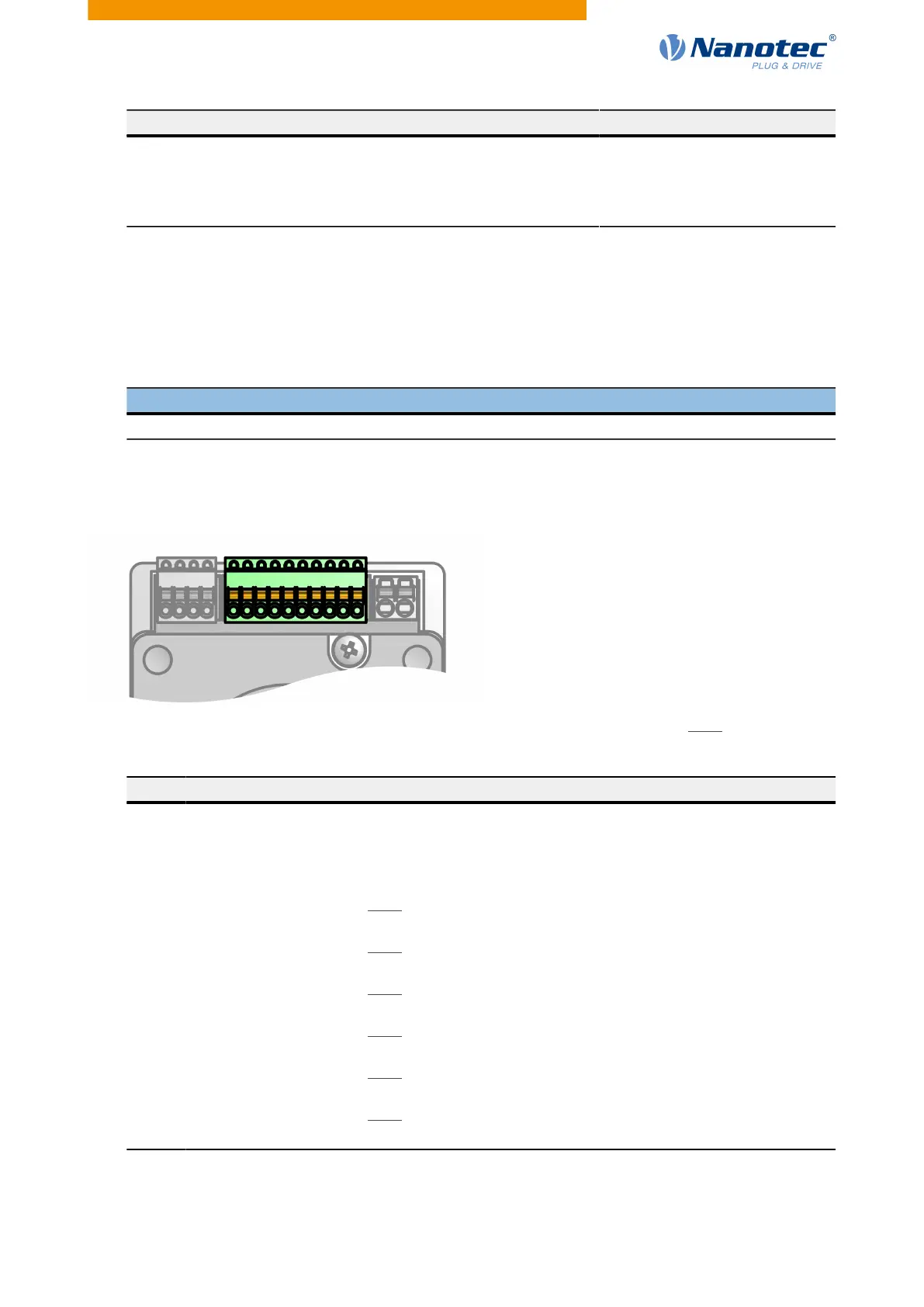
3.6.3 X2 – digital inputs
Connection for the digital inputs.
●
Type: Phoenix Contact MCV 0.5/10-G-2.5
●
Mating connector (included in scope of delivery): Phönix Contact FK-MCP 0.5/10-ST-2.5 (or equivalent)
Note
All inputs for clock-direction can be switched together between 5 V and 24 V.
Switching between 24 V (3240
h
:06="1") and 5 V (3240
h
:06="0") is performed via object 3240
h
as is switching
from "single-ended" (3240
h
:07="0") to "differential" (3240
h
:07="1").
Pin Function Note
1 Digital input 1 0/+24 V
2 Digital input 2 0/+24 V
3 Digital input 3 0/+24 V
4 -Release (-input 4) 5 V / 24 V signal, switchable by means of software with object
3240
h
, max. 1 MHz
5 +Release (+input 4) 5 V / 24 V signal, switchable by means of software with object
3240
h
, max. 1 MHz
6 –Direction (–input 5) 5 V / 24 V signal, switchable by means of software with object
3240
h
, max. 1 MHz
7 +Direction (+input 5) 5 V / 24 V signal, switchable by means of software with object
3240
h
, max. 1 MHz
8 –Clock (–input 6) 5 V / 24 V signal, switchable by means of software with object
3240
h
, max. 1 MHz
9 +Clock (+input 6) 5 V / 24 V signal, switchable by means of software with object
3240
h
, max. 1 MHz
10 GND
The following switching thresholds apply for inputs 1 to 3:
Version: 2.0.1 / FIR-v1650 19