5 General concepts
5.1.3 Closed Loop
5.1.3.1 Introduction
The closed loop theory is based on the idea of a control loop. A disturbance acting on a system should be
compensated for quickly and without lasting deviation to adjust the control variable back to the set point.
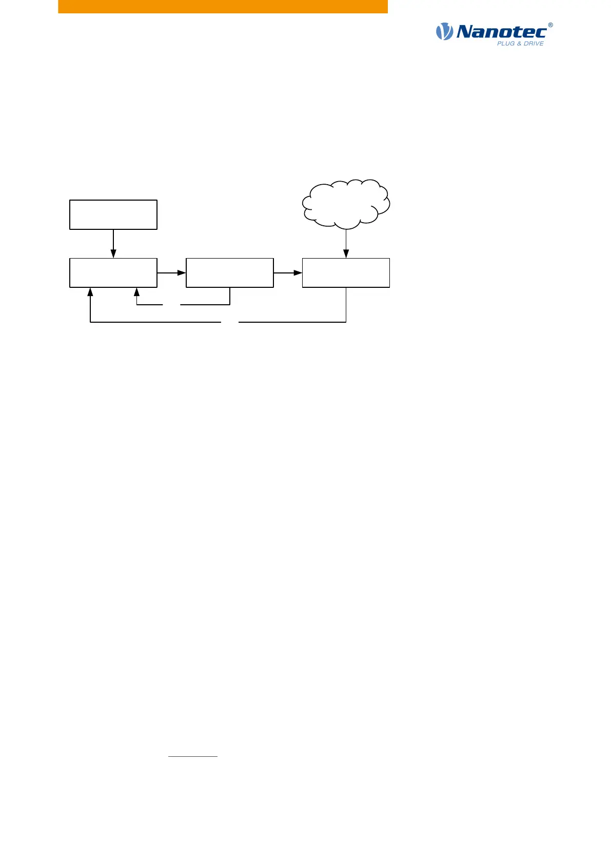
Closed loop using a speed control as an example:
Regulator
PI
I
, PI
V
Actuator
Current magnitude/current angle
Malfunction
Torque-
fluctuations
Control variable
Actual speed
I
actual
V
actual
Reference variable
Target speed
PI
I
= Proportional-integral current control loop
PI
V
= Proportional-integral velocity control loop
I
actual
= Actual current
V
actual
= Actual speed
The closed loop method is also referred to as "sine commutation via an encoder with field-oriented control".
At the heart of closed loop technology is the performance-adjusted current control as well as the feedback of
the actual values of the process. Using the encoder signals, the rotor orientation is recorded and sinusoidal
phase currents generated in the motor windings. Vector control of the magnetic field ensures that the
magnetic field of the stator is always perpendicular to that of the rotor and that the field strength corresponds
precisely to the desired torque. The current thereby controlled in the windings provides a uniform motor force
and results in an especially smooth-running motor that can be precisely regulated.
The feedback of the control variables necessary for closed loop mode can be realized with various
technologies. In addition to the physical feedback with encoders or Hall sensors, it is also possible to virtually
record the motor parameters through software-based model calculation. Physical variables, such as speed
or back-EMF, can be reconstructed with the help of a so-called "observer" from the data of the current
controller. With this sensorless technology, one has a "virtual rotary encoder", which – above a certain
minimum speed – supplies the position and speed information with the same precision as a real optical or
magnetic encoder.
All controllers from Nanotec that support closed loop mode implement a field oriented control with sine
commutated current control. Thus, the stepper motors and BLDC motor are controlled in the same way as a
servo motor. With closed loop mode, step angle errors can be compensated for during travel and load angle
errors corrected within one full step.
5.1.3.2 Commissioning
An auto setup must be performed before using closed loop mode. The auto setup operating mode
automatically determines the necessary parameters (e.g., motor data, feedback systems) that are necessary
for optimum operation of the field oriented control. All information necessary for performing the auto setup
can be found in chapter Auto setup.
With the Plug & Drive motors, it is not necessary to perform the auto setup, as this was already performed at
the factory.
Version: 2.0.1 / FIR-v1650 36