3 Technical details and pin assignment
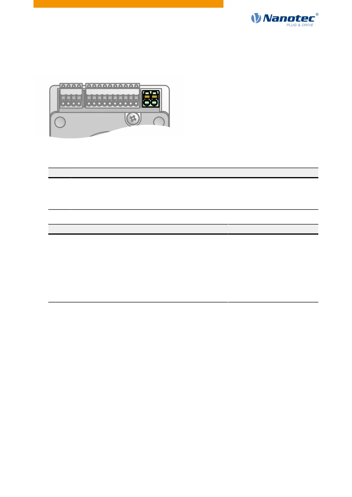
3.6.4.2 Connections
●
Type: Phoenix Contact MCV 1.5/ 2-G-3.5
●
Mating connector (included in scope of delivery): Phönix Contact FK-MCP 1.5/ 2-ST-3.5 (or equivalent)
Pin Function Note
1 +Vcc
●
PD4-C: 12-48 V, ±5%
●
PD4-CB: 12-24 V, ±5%
2 GND
Connection data min max
Conductor cross section, rigid, min. 0.2 mm
2
1.5 mm
2
Conductor cross section, flexible, min. 0.2 mm
2
1.5 mm
2
Conductor cross section, flexible, min. Wire-end sleeve without
plastic sleeve, min.
0.25 mm
2
1.5 mm
2
Conductor cross section, flexible, min. Wire-end sleeve min. Plastic
sleeve min.
0.25 mm
2
0.75 mm
2
Conductor cross section, min. AWG 24 16
Min. AWG acc. to UL/CUL 24 16
3.6.4.3 Permissible operating voltage
The maximum operating voltage is 50.5 V DC for the stepper motors (PD4-C) and 29 V for the BLDC motors
(PD4-CB). If the input voltage of the controller exceeds 51.5 V or 30 V, the motor is switched off and an error
triggered. Above 50.5 V DC for the stepper motors (PD4-C) and 29 V for the BLDC motors (PD4-CB), the
integrated ballast circuit (3 W power) is activated.
The minimum operating voltage is 11.4 V DC. If the input voltage of the controller falls below 10 V, the motor
is switched off and an error triggered.
A charging capacitor of at least 4700 µF / 50 V (approx. 1000 µF per ampere rated current) must be
connected in parallel to the supply voltage to avoid exceeding the permissible operating voltage (e.g., during
braking).
Version: 2.0.1 / FIR-v1650 21
 Loading...