Trainee Guide TR-L2-M2000
Level 2 Maintenance Training – M2000 Dispensing Systems 2-2-25 P/N 73-0018-00 (Revision B)
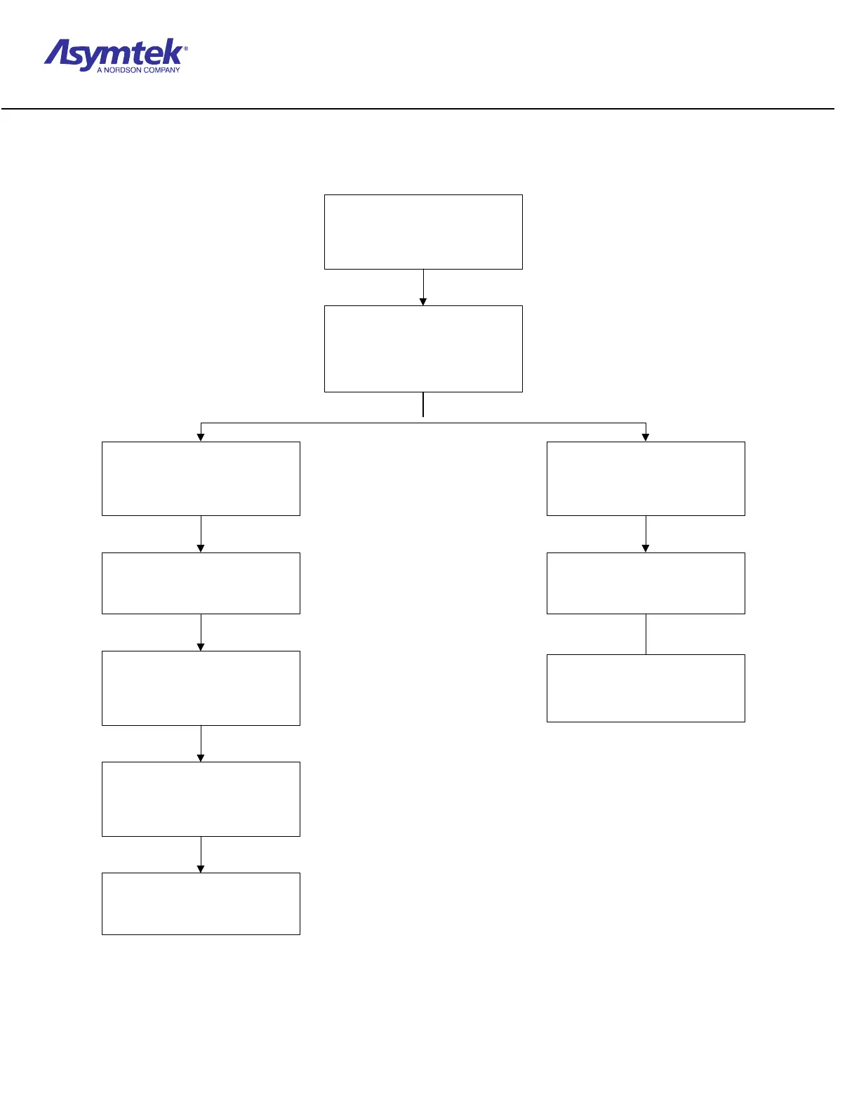
Diagram Sheet 2-4-5
Stop Pin/Clamp Bar/Lift Table Raises
Board Sensor
y
Detects a part entering the system.
y
Triggers output to Interconnect
PCA.
Interconnect PCA
y
Receives Board Sensor input.
y
Relays message to Conveyor
Controller Module and Interface
PCA.
Conveyor Controller Module
y
Receives Board Sensor input.
y
Sends a "Stop Pin Up" message to
the Interconnect PCA.
Interface PCA
y
Receives Board Sensor input.
y
Sends a "Start Timer" output to the
Interconnect PCA.
Interconnect PCA
y
Relays "Start Timer" message to
the Timers Module.
Timers Module
y
Begins counting to determine
minimum amount of time part will
remain in current station.
Interconnect PCA
y
Relays "Stop Pin Up" message to
Interface PCA.
Interface PCA
y
Relays "Stop Pin Up" message
back to Interconnect PCA.
Interconnect PCA
y
Relays "Stop Pin Up" message to
the Pneumatic Solenoid for the
specific stop pin.
Pneumatic Solenoid
y
Activates to raise the stop pin. *
*The electrical and pneumatic path for lift tables and clamp bars is identical to this one described for stop pins.
 Loading...


