• If the specified Axis is enabled by the MC_GroupEnable (Enable Axes Group) instruction, the
MC_T
ouchProbe (Enable External Latch) instruction causes an error and is not executed.
• For each axis, you can specify LatchID to execute up to two MC_TouchProbe (Enable External
Latch) instructions at the same time.
• LatchID is also used to specify the latch to abort for the MC_AbortTrigger (Disable External Latch)
instruction.
Additional Information
• Latching a position is also possible if an encoder axis that is connected to an OMRON GX-
series GX-EC02££ EtherCA
T Encoder Input Slave is used.
• If you use an NX-series Pulse Output Unit, you can also perform latching with this instruction.
Refer to the NX-series Position Interface Units User’s Manual (Cat. No. W524) for details.
Trigger Input Condition
Select the trigger conditions with Mode, LatchID, and InputDrive of the T
riggerInput (Trigger Input Con-
ditions) variable.
Mode
• Mode can be set to Drive Mode to specify a signal from the Servo Drive or other device as the trig-
ger, or to Controller Mode to specify a trigger with TriggerVariable.
• The trigger occurs on the rising edge of the trigger signal. The axis position is latched on the first
trigger (FALSE to TRUE) after the MC_TouchProbe instruction is executed.
• While this instruction is Busy (Executing), a change in TriggerVariable is taken as a trigger even if
Execute is FALSE.
Additional Information
Set Mode to _mcDrive
(Servo Drive Mode) if you use an OMRON GX-series GX-EC02££
EtherCAT Encoder Input Slave.
Drive Mode
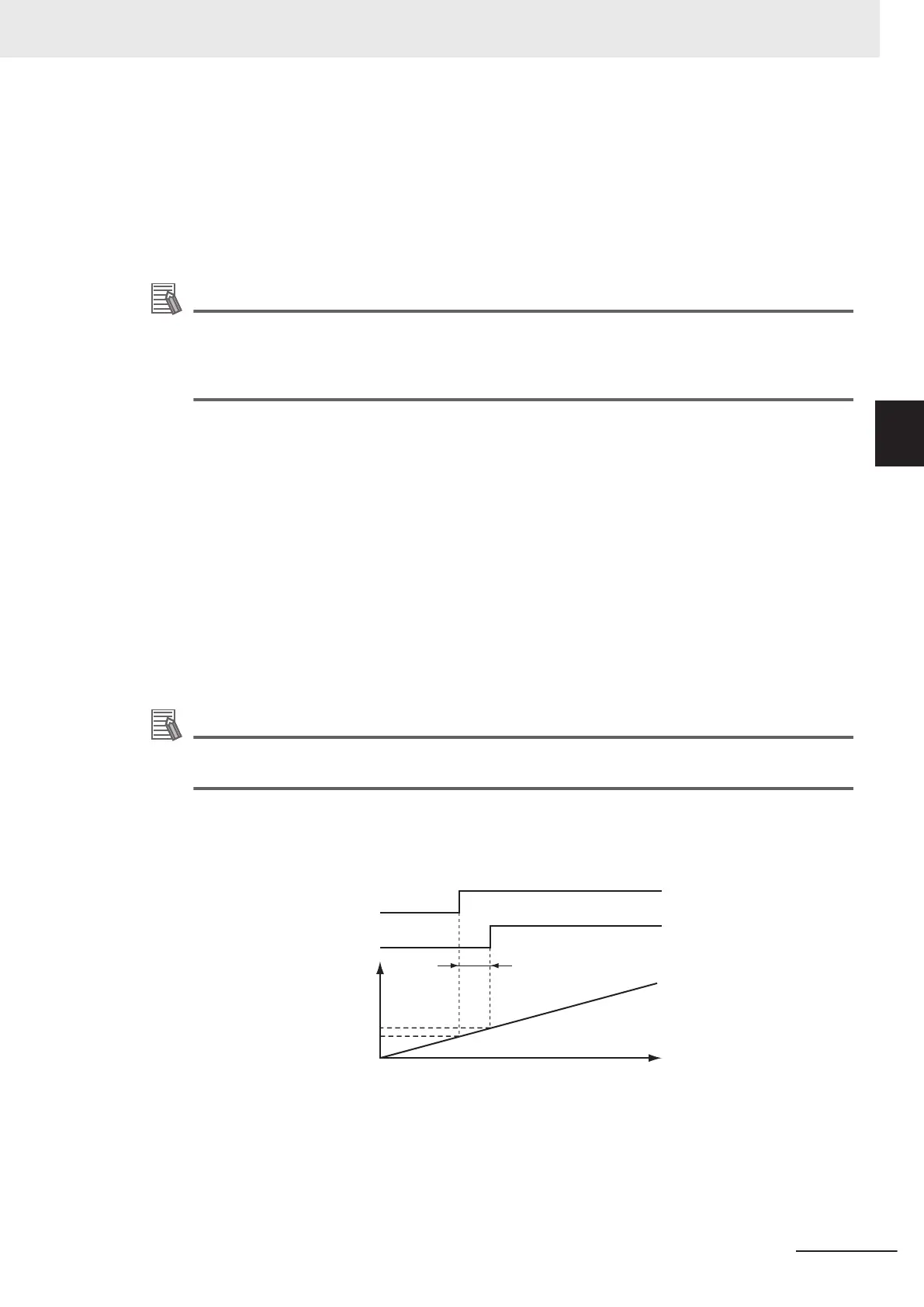
For trigger detection and latching of the actual position, the latched actual position is more precise in
Drive Mode (which is a function of the Servo Drive or other device) than it is in Controller Mode.
Time
Position (latched position)
Position when trigger signal is input
Input f
ilter delay
Axis position
Trigger detection
Input signal to Servo Drive
3 Axis Command Instructions
3-365
NY-series Motion Control Instructions Reference Manual (W561)
MC_TouchProbe
3
Function