*2. Define a user-defined variable with a data type of _sTRIGGER_REF.
_sTRIGGER_REF
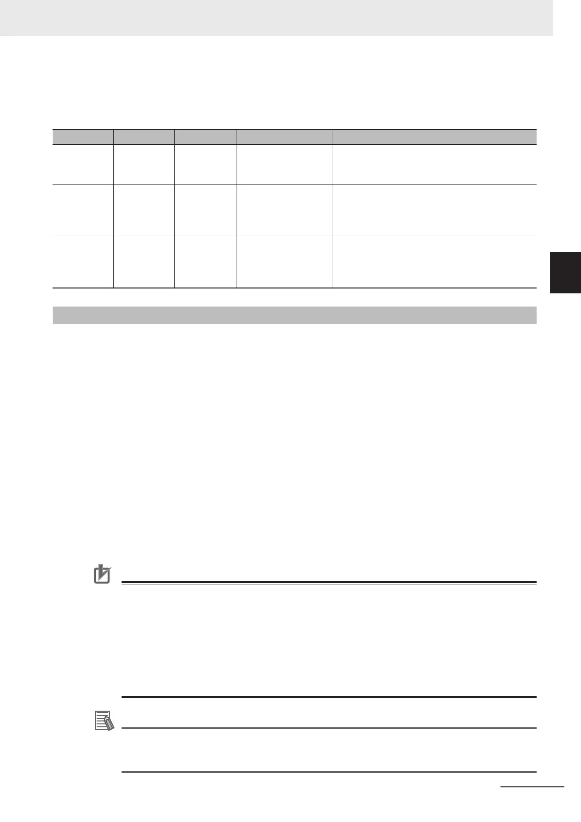
Name Meaning Data type Valid range Function
Mode Mode _eMC_TRIG-
GER_MODE
0: _mcDrive
1: _mcController
Specify the trigger mode.
0: Drive Mode
1: Controller Mode
LatchID Latch ID Se-
lection
_eMC_TRIG-
GER_LA
TCH
_ID
0: _mcLatch1
1: _mcLatch2
Specify which of the two latch functions to use in
Drive Mode.
0: Latch 1
1: Latch 2
InputDrive Trigger Input
Signal
_eMC_TRIG-
GER_IN-
PUT_DRIVE
0: _mcEncoderMark
1: _mcEXT
Specify the Servo Drive trigger signal to use in
Drive Mode.
0: Z-phase signal
1: External input
Function
• When Execute changes to TRUE, the axis travels with absolute travel, relative travel, or velocity
control depending on the MoveMode setting.
•
The target position is set in Position (Target Position) for absolute travel. The target distance is set in
Position (Target Distance) for relative travel.
Both travel methods use Velocity (Target Velocity) for travel operation.
• Relative positioning is performed with FeedVelocity from the actual position where the external input
turned ON during travel for the feed distance that is specified with FeedDistance.
• If no interrupt signal is input before the axis reaches the default target position during interrupt feed-
ing in absolute or relative travel mode, the axis stops at the target position.
You can specify whether there is an error output when the axis stops for ErrorDetect (i.e., when
there is no interrupt input.) If you specify an error output, CommandAborted changes to TRUE, and
Busy (Executing) and Active (Controlling) change to FALSE.
• To use interrupt masks, change WindowOnly to TRUE, then specify FirstPosition and LastPosition.
Interrupt feeding is performed for the first interrupt signal generated by the actual position between
the FirstPosition and the LastPosition.
Precautions for Correct Use
• Feeding after the interrupt is performed as a relative movement for the distance that is speci-
fied with FeedDistance. If a positive value is specified for FeedDistance, feeding is performed
in the same direction as before the interrupt input, and if a negative value is specified, feeding
is performed in the opposite direction.
•
The setting of the Operation Selection at Reversing axis parameter is used for the acceler-
ation and deceleration rates when reversing to feed.
• If an underflow or overflow would occur for the position after interrupt feeding, an error occurs
when the interrupt input is received. If an interrupt input is received after there is an overflow
or underflow, an axis error will still occur.
Additional Information
Refer to MC_MoveAbsolute on page 3-
53 for absolute travel, MC_MoveRelative on page 3-80
for relative travel, MC_MoveVelocity on page 3-88 for velocity control, and WindowOnly on
page 3-118 for WindowOnly.
3 Axis Command Instructions
3-115
NY-series Motion Control Instructions Reference Manual (W561)
MC_MoveFeed
3
Function