EasyManua.ls Logo

Omron Sysmac NY-series User Manual

Omron Sysmac NY-series
744 pages
To Next Page IconTo Next Page
To Previous Page IconTo Previous Page
Page #418 background imageLoading...
Page #418 background image
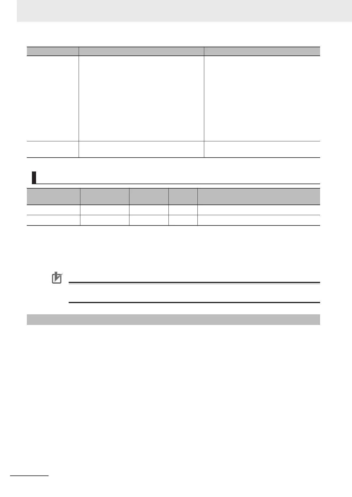
Name Timing for changing to TRUE Timing for changing to FALSE
CommandAborted
When this instruction is aborted because anoth-
er motion control instruction was executed with
the Buf
fer Mode set to Aborting.
When this instruction is canceled due to an er-
ror.
When this instruction is executed while there is
an error.
When you start this instruction during MC_Stop
instruction execution.
When execution of the synchronized control in-
struction is completed.
When Execute is TRUE and changes to
FALSE.
After one period when Execute is FALSE.
Error When there is an error in the execution conditions
or input parameters for the instruction.
When the error is cleared.
In-Out Variables
Name Meaning Data type
Valid
range
Description
Master Master Axis _sAXIS_REF ---
Specify the master axis.
*1
Slave Slave Axis _sAXIS_REF ---
Specify the slave axis.
*1
*1. Specify a user-defined Axis Variable that was created in the Axis Basic Settings of the Sysmac Studio (default: MC_Ax-
is*) or a system-defined axis variable name (_MC_AX[*]).
If you use Sysmac Studio version 1.29 or higher
, you can specify the system-defined axis variable name for AT specifi-
cation of a user-defined variable. This will allow you to specify the user-defined variable.
If you use Sysmac Studio version 1.28 or lower, do not specify any user-defined variable created in the variable table.
Precautions for Correct Use
If you specify the same axis for the master axis and slave axis, a Master and Slave Defined as
Same Axis minor fault (error code 5436 hex) will occur
.
Function
Except during execution of the MC_CombineAxes instruction, if the MC_Phasing instruction is exe-
cuted when single-axis synchronized control is in progress, the phase of the master axis is shifted
according to the settings of PhaseShift (Phase Shift Amount), V
elocity (Target Velocity),
Acceleration (Acceleration Rate), and Deceleration (Deceleration Rate).
The command current position and actual current position of the master axis do not change, and the
relative shift between the command current position and actual current position of the master axis is
taken as the phase of the master axis.
The slave axis is synchronized to the shifted master axis phase.
Done changes to TRUE when the PhaseShift (Phase Shift Amount) is reached.
Shifting is ended when execution of the synchronized control instruction is completed. If a synchron-
ized control instruction is executed again, the previous amount of shift is not affected.
You can shift the phase of the master axis for the following synchronized control instructions:
MC_CamIn (Start Cam Operation), MC_GearIn (Start Gear Operation), MC_GearInPos (Positioning
Gear Operation), and MC_MoveLink (Synchronous Positioning).
3 Axis Command Instructions
3-330
NY-series Motion Control Instructions Reference Manual (W561)

Table of Contents

Question and Answer IconNeed help?

Do you have a question about the Omron Sysmac NY-series and is the answer not in the manual?

Omron Sysmac NY-series Specifications

General IconGeneral
CategoryControl Unit
Operating Temperature0 to 55 °C
Power Supply Voltage24 VDC
Power Supply24 VDC
Product SeriesNY-series
CPUIntel Atom or Intel Core i7
Programming LanguagesIEC 61131-3 (LD, FBD, ST, SFC)
Memory (Program)Up to 64 MB
Ethernet Ports2
EtherNet/IP Ports2 ports (built-in)
EtherCAT Master Ports1
EtherCATYes
Motion ControlSupported
SafetyYes
Built-in I/ONo
Relative Humidity10 to 90% (non-condensing)
Vibration Resistance5 to 8.4 Hz: 3.5 mm; 8.4 to 150 Hz: 9.8 m/s²
Shock Resistance147 m/s²
Power ConsumptionVaries by model
CertificationsCE, cULus, RCM, KC, EAC

Summary

Introduction to Motion Control Instructions

Variables and Instructions

Axis Command Instructions

MC_Power

Explains the MC_Power instruction for making a Servo Drive ready to operate.

MC_MoveJog

Explains the MC_MoveJog instruction for jogging an axis according to the specified target velocity.

MC_Home

Explains the MC_Home instruction for operating the motor to determine home.

MC_HomeWithParameter

Explains the MC_HomeWithParameter instruction for setting homing parameters and operating the motor to determine home.

MC_Move

Explains the MC_Move instruction for performing absolute positioning or relative positioning.

MC_MoveAbsolute

Explains the MC_MoveAbsolute instruction for moving the axis to a specified absolute target position.

MC_MoveRelative

Explains the MC_MoveRelative instruction for moving the axis the specified travel distance.

MC_MoveVelocity

Explains the MC_MoveVelocity instruction for performing velocity control.

MC_MoveZeroPosition

Explains the MC_MoveZeroPosition instruction for positioning to an absolute position of 0.

MC_Stop

Explains the MC_Stop instruction for decelerating an axis to a stop.

MC_ImmediateStop

Explains the MC_ImmediateStop instruction for stopping an axis immediately according to the specified stopping mode.

MC_CamIn

Explains the MC_CamIn instruction to start cam operation using a specified cam table.

MC_GearIn

Explains the MC_GearIn instruction to specify the gear ratio and start gear operation.

MC_GearInPos

Explains the MC_GearInPos instruction to perform electronic gear operation with specified gear ratio.

MC_MoveLink

Explains the MC_MoveLink instruction for positioning in sync with the specified master axis.

MC_TorqueControl

Explains the MC_TorqueControl instruction to control torque using the Torque Control Mode.

MC_SetTorqueLimit

Explains the MC_SetTorqueLimit instruction to limit torque output from the Servo Drive.

MC_TouchProbe

Explains the MC_TouchProbe instruction to record axis position when a trigger signal occurs.

MC_SyncMoveVelocity

Explains the MC_SyncMoveVelocity instruction for outputting target velocity in CSV Mode.

MC_SyncMoveAbsolute

Explains the MC_SyncMoveAbsolute instruction to cyclically output target positions.

MC_Reset

Explains the MC_Reset instruction to clear axis errors.

MC_DigitalCamSwitch

Explains the MC_DigitalCamSwitch instruction to turn a digital output ON or OFF based on axis position.

Axes Group Instructions

Common Command Instructions

Related product manuals