Precautions for Correct Use
• This instruction is not sufficient to actually turn digital outputs ON and OFF.
•
If you use an NX-series Encoder Input Unit, this instruction requires that time stamping is op-
erating.
Time stamping is not possible in the following cases.
a) An Encoder Input Unit or Servo Drive that does not support time stamping is used.
b) Object 6010 hex (Time Stamp) in the NX-series Encoder Input Unit is not assigned to a
PDO.
c) The Enable Distributed Clock in the EtherCAT Coupler Unit is Disabled (FreeRun).
• If you use an OMRON 1S-series Servo Drive with built-in EtherCAT communications, this in-
struction is not possible in the following cases.
a) Object 3211-83 hex (Present Position Time Stamp) in the OMRON 1S-series Servo Drive
with built-in EtherCAT communications is not assigned to a PDO.
b) The Enable Distributed Clock in the OMRON 1S-series Servo Drive with built-in Ether-
CAT communications is Disabled (FreeRun).
• An error does not occur for this instruction even if the time stamp is not updated. The
ON/OFF time will be calculated, but the result will not be the intended value.
Use this instruction only after you confirm in the MC Monitor Table or Watch Tab Page of the
Sysmac Studio that the TimeStamp member of the Axis Variable is being updated.
• If you use this instruction together with the NX_AryDOutTimeStamp instruction and with a
Digital Output Unit that supports time stamp refreshing, the minimum ON/OFF range will be
proportional to the value of the task period and the value of the rotation rate.
For example, the minimum ON/OFF range would be 5° if one rotation of the rotary table is
360°, the rotation rate is 800 r/min, and the task period is 500 µs. The minimum ON/OFF
range would become 10° if the task period was increased to 1,000 µs.
• Set the values of the FirstOnPosition, LastOnPosition, and Duration in the switch structure
variable so that the ON/OFF range of the digital output is larger than the minimum ON/OFF
range. If it is smaller than the minimum ON/OFF range, the actual digital output may not turn
ON or OFF.
• This instruction calculates the time stamp for when the specified position is reached based on
both the current position and current velocity of the axis. The accuracy of the calculated
stamp times is influenced by the encoder resolution and the rotation rate of the axis. The er-
ror will increase if the encoder resolution is low or the rotation rate of the axis is slow. You can
calculate a guideline for the maximum error with the following formula.
Maximum error in time stamp (s) = 180/(Encoder resolution (pulses/rotation) × rotation rate(r/
min))
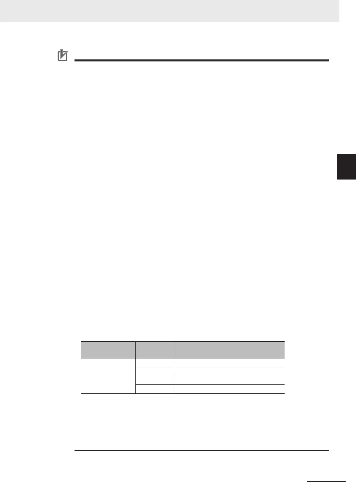
Some examples of the maximum error in time stamps for the encoder resolution and rotation
rate are given in the following table.
Encoder resolution
(pulses/rotation)
Rotation rate
(r/min)
Maximum error in calculated time stamps
(μ
s)
3600 400 ±125.0
800 ±62.5
131072 400 ±3.4
800 ±1.7
If the axis accelerates or decelerates quickly, the calculation error may increase. Use this in-
struction when the axis is at a constant velocity
.
Verify operation sufficiently to confirm safety.
• If you specify an unused axis or if the MC Test Run is in progress, Busy will change to TRUE
and InOperation and Error will change to FALSE when Enable changes to TRUE.
• Do not create two instances with the same instance name. If you do, unintentional outputs
may occur.
3 Axis Command Instructions
3-419
NY-series Motion Control Instructions Reference Manual (W561)
MC_DigitalCamSwitch
3
Function