Installing the Drive 3-71
DC590+ Series DC Digital Drive
Tightening the Drive
When all the bolts are in place, tighten them to the following torques:
• mounting bolts (4 per phase assembly) : 32Nm (23.6 ft.lbf)
• fishplate bolts : 32Nm (23.6 ft.lbf)
Reminder : Remove the "temporary hanging" bolts.
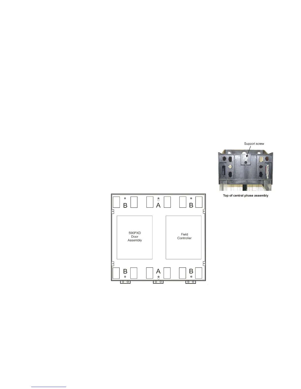
Fitting the Control Panel Assembly
Fit the M6 x 16mm support screw assemblies [screw, single coil spring washer & plain washer] (A) to the
central phase assembly (as shown opposite) and to the equivalent position at the bottom of the phase
assembly. Screw them in only part of the way so that the control panel assembly can hang from them.
Offer-up the control panel assembly and hang it from the two central support screws (A).
Secure the gantry using the M6 x 16mm support screw assemblies (B).
Tighten all screws to 4.5Nm (3.3 ft.lbf).

 Loading...


