Serial Communications A-5
DC590+ Series DC Digital Drive
5703 Support
The 5703 Setpoint Repeater Unit provides the facility to run a line of drives in speed-lock without the use of a 5720 Quadraloc controller; for accurate
speed-holding, encoder feedback is required. Ratioed speed-locking is supported, although the unit is not intended to replace the Quadraloc in
applications requiring high accuracy.
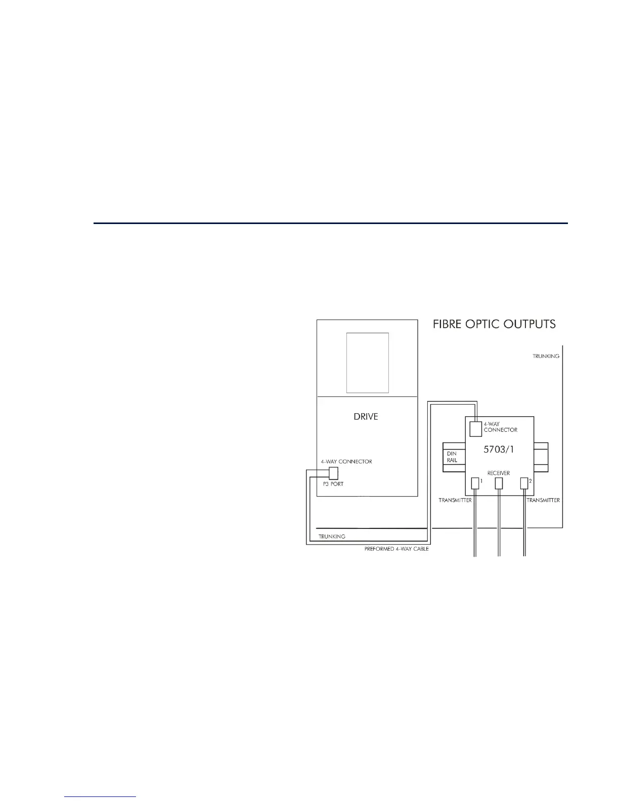
A 16-bit speed signal is passed between drives via the P3 port on each Drive (a port otherwise used only off-line for the upload and download of
EEPROM data). The port operates RS232 compatible signal levels. The 5703/1 converts these signal levels to fibre optic signals for transmission, and
from fibre optics to RS232 for reception. Alternatively an external converter may be used to provide galvanic isolation and to convert the signals to
RS485 for transmission over longer distances than is recommended for RS232.
Hardware Description
The 5703 is housed in a DIN rail mounted box and is
provided with a cable to connect into the P3 port. The
cable is 400mm long to limit transmission errors, the
primary unit-to-unit interconnection is intended to be
achieved by a fibre optic cable.
The 5703 unit itself is simply an electric signal-to-light
converter and does not alter the signal in any way, this is
achieved within the software data of the Drive.
It is fitted with one fibre optic receiver and two fibre optic
transmitters, the fibre optic receiver has a fixed function to
receive data from the preceding unit while the transmitter
sends data to the following unit. The additional transmitter
can be used either to re-transmit the incoming signal or
provide a second transmission of the output signal, this
gives the unit wide functionality. When the link is in the
normal right hand position, assuming the board is
mounted with the fibre optics downward, the second
transmitter repeats the output signal. In the left hand
position it repeats the input signal.
The 5703/1 can be configured to point to any relevant
parameter in the block diagram, the default connections
are such that the scaled input is connected to the
"additional speed demand" and the output to the "speed
demand".
Figure A- 1 5703/1 Product Outline Drawing

 Loading...


