EasyManuals Logo

Parker 590+ series User Manual

Parker 590+ series
545 pages
To Next Page IconTo Next Page
To Previous Page IconTo Previous Page
Page #235 background imageLoading...
Page #235 background image
Routine Maintenance and Repair 8-11
DC590+ Series DC Digital Drive
Repairs for Frame H
Fuse Replacement (Frame H)
1. Remove the front cover.
2. Unplug the ribbon cables to the trigger boards.
3. Open the swing-frame using the two quick-release fixings at the right hand end.
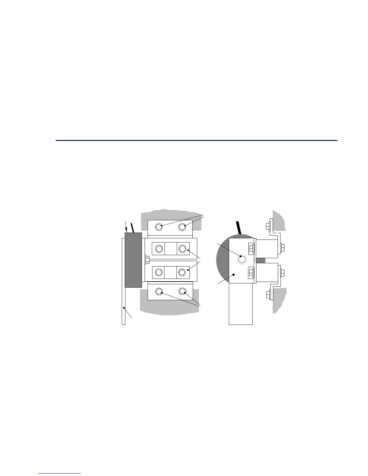
590+ 4Q Product (Regenerative)
Upper Phase Assembly
Lower Phase Assembly
Current
Transformer
AC Incoming
Busbar
Fuse
Phase Assembly
Connection Screws
Screw
A
B
C
D
E
Handles
FRONT VIEW SIDE VIEW
Phase Assembly
Connection Screws
Fuse
FG
HI
CT Plate
Figure 8-1 590+ (Frame H) Fuse Replacement Diagram

Table of Contents

Questions and Answers:

Question and Answer IconNeed help?

Do you have a question about the Parker 590+ series and is the answer not in the manual?

Parker 590+ series Specifications

General IconGeneral
Control ModeSpeed, Torque, Position
Operating Temperature0°C to 40°C
AltitudeUp to 1000 m without derating
Speed Regulation0.01% of base speed
Communication OptionsEthernet, Profibus, CANbus, Modbus, DeviceNet
Feedback OptionsTachometer, Encoder
Protection RatingIP20
Storage Temperature-25°C to 55°C
Relative Humidity5% to 95% (non-condensing)

Related product manuals