Technical Specifications E-17
DC590+ Series DC Digital Drive
Terminal Definitions (Digital/Analog Inputs & Outputs)
User inputs are IEC1131 compliant. Terminal blocks A, B, and C are located on the control board each block being a 9 way plug-in connector. In
addition to terminal blocks A, B and C, terminal blocks G and H provide connections when the two option modules are fitted on the control board.
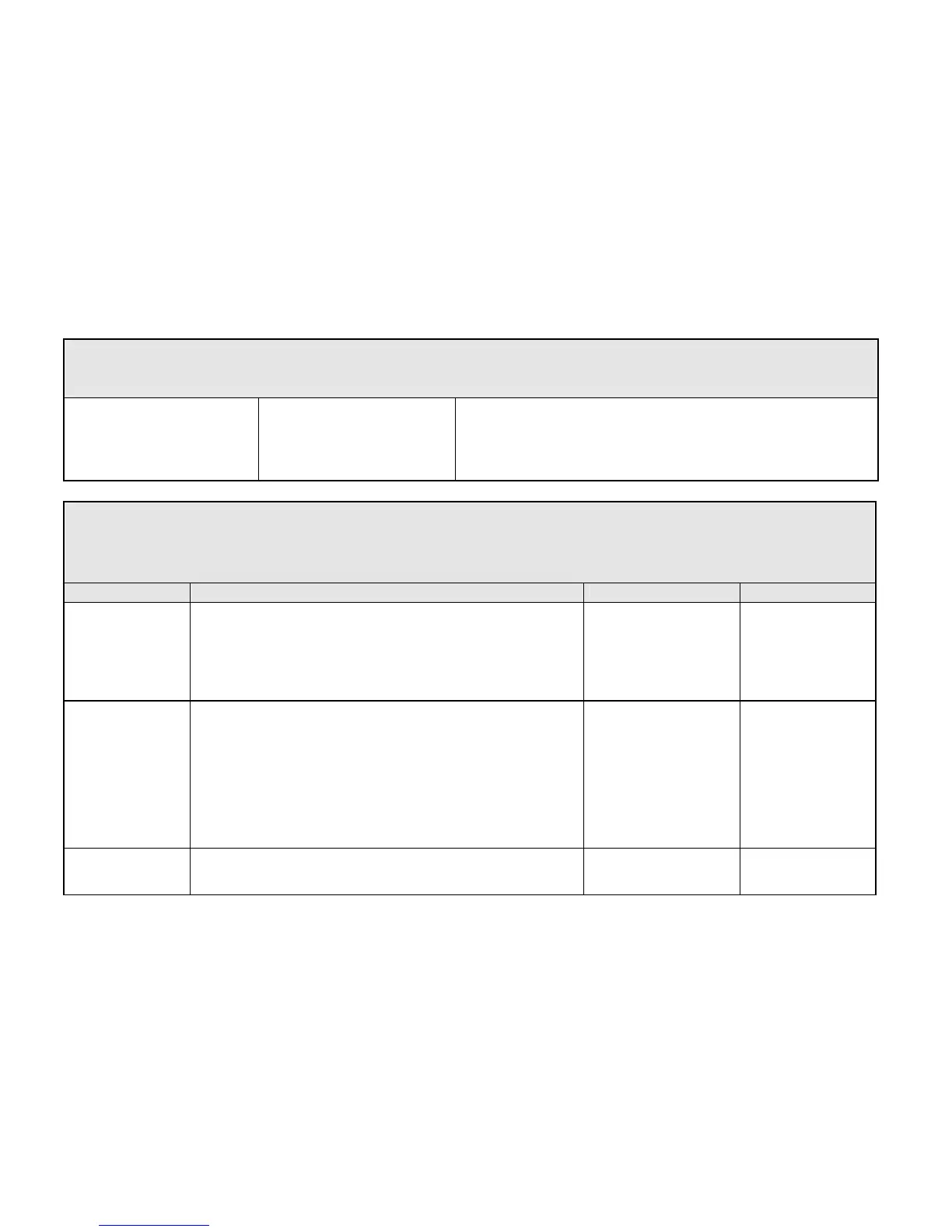
Analog Output
Output Resolution
Output Drive Capacity
Update Interval
Settling Time
Output Overdrive Capability
Overload Protection
11 Bit plus sign, i.e. 5mV resolution, equals 0.05% of full scale deflection
10V at 5mA max.
5ms
5ms, for 0% to 90%
+10%, i.e. maximum output +/-11V at 2.5mA max.
Indefinite short circuit protection provided
Terminal Information - Power Board (Frames 1-5)
Note that on Frame 1 and 2 units, L1, L2, L3, A+ and A- terminals are located on a separate Terminal Board. On Frame 3, 4 & 5 units, they are
busbar connections.
Frame 3 units have terminal designations D1 to D8, shown in brackets in the Terminal Number column of this table.
Terminal Description Terminal Function Signal Level Terminal Number
Mains Supply L1 Three phase mains power input, phase reference Line 1 Refer to Power Supply
Details, page E-
E-8.
L1
Mains Supply L2 Three phase mains power input, phase reference Line 2 Refer to Power Supply
Details, page E-
E-8.
L2
Mains Supply L3 Three phase mains power input, phase reference Line 3 Refer to Power Supply
Details, page E-
E-8.
L3
Armature connection
positive
A+
Drive dc power output, reference Armature Positive connection to dc motor Maximum voltage dependent
upon the supply voltage, the
ratio being:
Vout is approximately equal
to 1.15Vac supply
A+
Armature connection
negative
A-
Drive dc power output, reference Armature Negative connection to dc motor Maximum voltage dependent
upon the supply voltage, the
ratio being:
Vout is approximately equal
to 1.15Vac supply
A-
Auxiliary N/C Volt-
Free MC Contact : 1,
2
Used to indicate the status of the main contactor (L1, L2, L3). See TB4. - 1, 2

 Loading...


