3-72 Installing the Drive
DC590+ Series DC Digital Drive
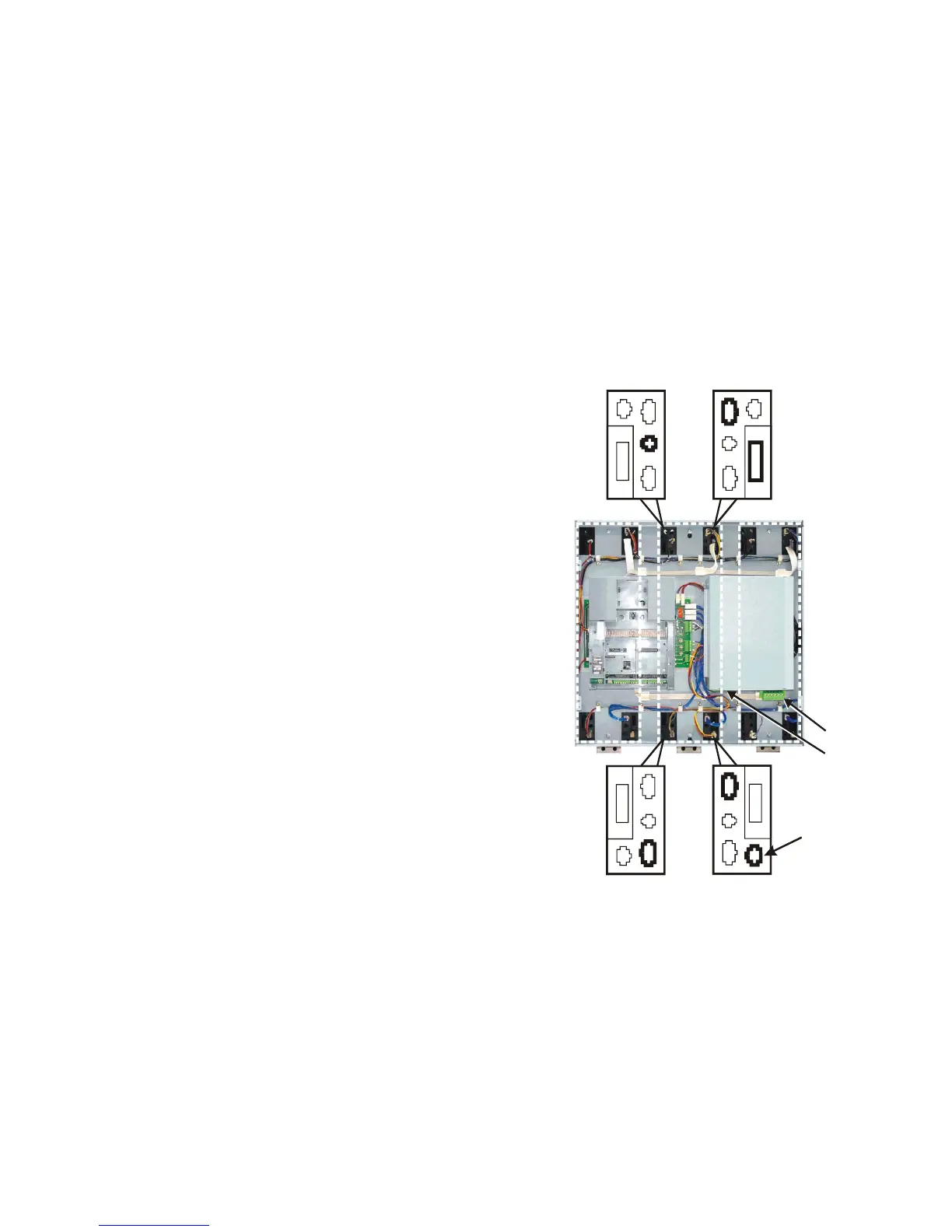
Terminal Connections
The control panel assembly has connectors for each phase assembly. These are
secured in such a way that the cables will only reach the correct terminals set: 1, 2,
3 or 4.
NOTE Terminal sets 3 & 4 feature similar 6-way connectors, however
one is a male connector and the other a female, so they can't be
fitted incorrectly.
Complete the same connections for each phase assembly, plus make the additional
armature voltage feedback connection to the central Phase Assembly (shown
below). Make sure the terminals are clipped together correctly.
Fit the push-fit control terminals (A) from the control panel assembly. Fit the
screw-in power terminals (B).
This completes the building of the DC590+ Drive (other than attaching the front
cover).
12
A
3 4
B
This connection
is only used
on the central
Phase Assembly

 Loading...


