Serial Communications A-1
DC590+ Series DC Digital Drive
System Port (P3)
This port has several uses:
Drive Connections
The port is an un-isolated RS232, 9600 Baud (default), supporting the standard EI BISYNCH ASCII communications protocol. Contact Parker SSD
Drives for further information.
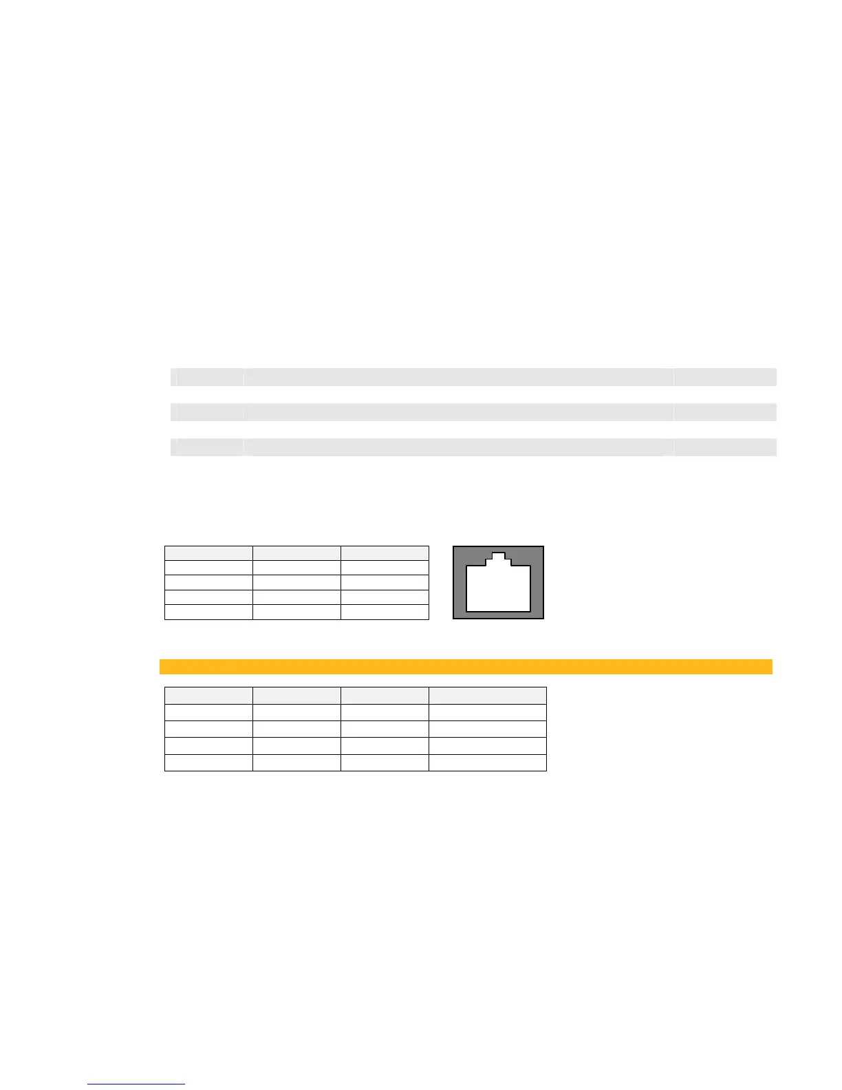
Use a standard P3 lead to connect to the Drive.
P3 Port Pin Lead Signal
1 Black 0V
2 Red 24V
3 Green TX
4 Yellow RX
6-Way Lead to DB9/DB25 Connector
IMPORTANT
There is 24V present on pin 2 of the P3 port. This may damage your PC or the Drive.
P3 Port Pin Lead Female DB9 Pin Female DB25 Pin
1 Black 5 7
2 Red not connected not connected
3 Green 2 3
4 Yellow 3 2
UDP Support
Upload information from a PC Refer to page A-2
DSE Lite
Parameters can be monitored and updated by DSE Lite (or other suitable PC programming tool) Refer to page
A-4
5703 Support
Connection for a Parker SSD Dries' 5703 Setpoint Repeater Unit Refer to page A-5
EI ASCII
Communications with other control/supervisory equipment Refer to page
A-8
EI BINARY
Communications with other control/supervisory equipment Refer to page A-13
1 2 3 4
PORT

 Loading...


