Programming D-89
DC590+ Series DC Digital Drive
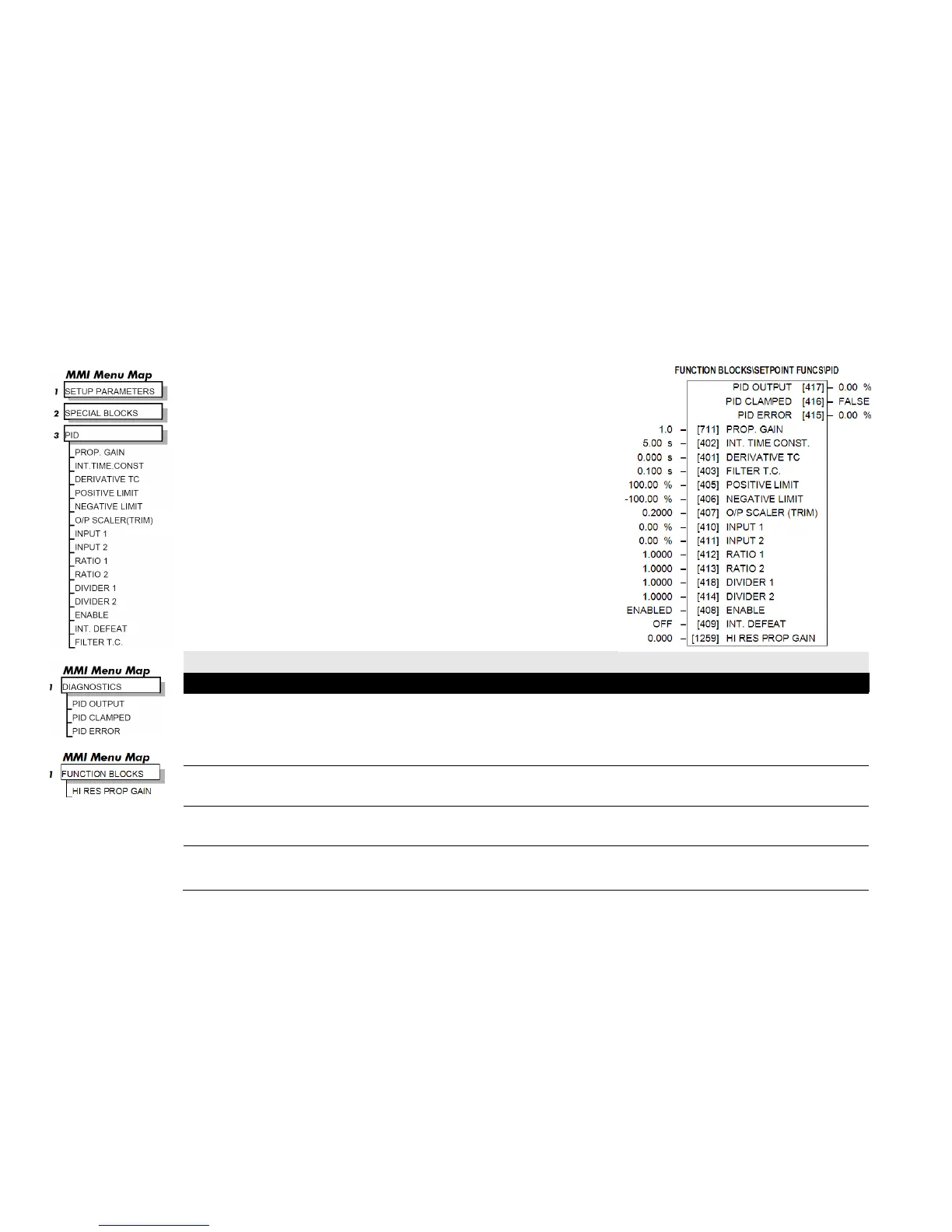
PID
This is a general purpose PID block which can be used for many different closed loop
control applications.
The PID feedback can be loadcell tension, dancer position or any other transducer feedback
such as pressure, flow etc.
This block is ignored by the drive unless SYSTEM::CONFIGURE I/O::BLOCK
DIAGRAM::PID O/P DEST is connected to a non-zero tag.
Features:
• Independent adjustment of gain and time constants.
• Additional first-order filter (F).
• Functions P, PI, PD, PID with/without F individually selected.
• Ratio and divider for scaling each input.
• Independent positive and negative limits.
• Output scaler (Trim).
• Gain profiled by diameter for centre-driven winder control.
PID
PROP. GAIN 711 0.0 to 100.0
The maximum limit of the proportional gain. This is a pure gain factor which shifts up or down the whole Bode PID transfer function leaving the
time constants unaffected. A value of P = 10.0 means that, for an error of 5%, the proportional part (initial step) of the PID output will be: 10 x [ 1
+ (Td/Ti) ] x 5 %, i.e. approx. 50% for Td << Ti. Also refer to HI RES PROP GAIN below.
INT. TIME CONST. 402 0.01 to 100.00 s
The integral time constant (Ti)
DERIVATIVE TC 401 0.000 to 10.000 s
The derivative time constant (Td). Set this value to 0.000 to remove the derivative term.
A first-order filter for removing high frequency noise from the PID output. When set to 0.000 the filter is removed. The high frequency lift of the
transfer function is determined by the ratio k of the Derivative Time Const (Td) over the Filter Time Constant (Tf) - typically 4 of 5.

 Loading...


