Installing the Drive 3-37
DC590+ Series DC Digital Drive
Power Board Circuit Descriptions
AH470280U001, U002, U003, U004 (Frame 1)
(2 Quad and 4 Quad)
Power supplies for the controller are generated from the single
phase auxiliary supply via a Switched Mode Power Supply. The
incoming supply is directly rectified to provide a high voltage dc
power rail. A high voltage transistor switches this rail on to the
primary of a high frequency transformer, the output of which is
rectified and smoothed to provide the dc power supply rails. The
+15V dc rail is monitored via a reference element and a control
signal returned via an opto-isolator to the control element of the
high voltage switching transistor. The other dc rails (-15V & +24V
dc) are generated via separate secondary windings which are
rectified and smoothed, with a separate SMPS element providing a
regulated +5V dc rail. The SMPS operates over a0n input voltage
range of 110V to 240V ac 10%, 50/60Hz.
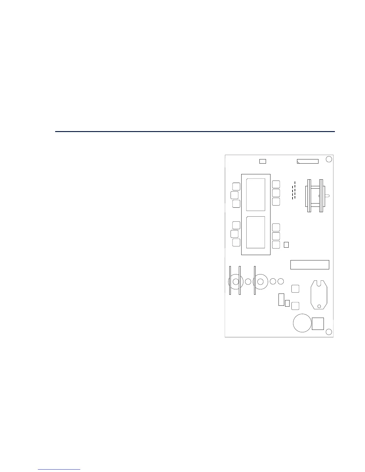
Figure 3- 13 590+ Power Board 4 Quad
CONN 26
CONN 4
TP6
TP1
TP4
TP8
TP5
TP7
TP3
TP9
TP2
T15
T11
T9
T7
T8
T12
T10
T5
T3
T1
T2
T6
T4
CONN 24
TH 3
TH 2
TH1
T20
T21
TB3
RLY1
CONN 2
TB9TB8
TB7
TB6
TB5
LK8 LK9
LK10
CONN 1
TB4
(to control board)
(to heatsink thermistor)
heatsink
(to fan 24V dc)
(to terminal board)
("motor" - 2Q)
("regen" - 4Q)
CT
CT

 Loading...


