D-104 Programming
DC590+ Series DC Digital Drive
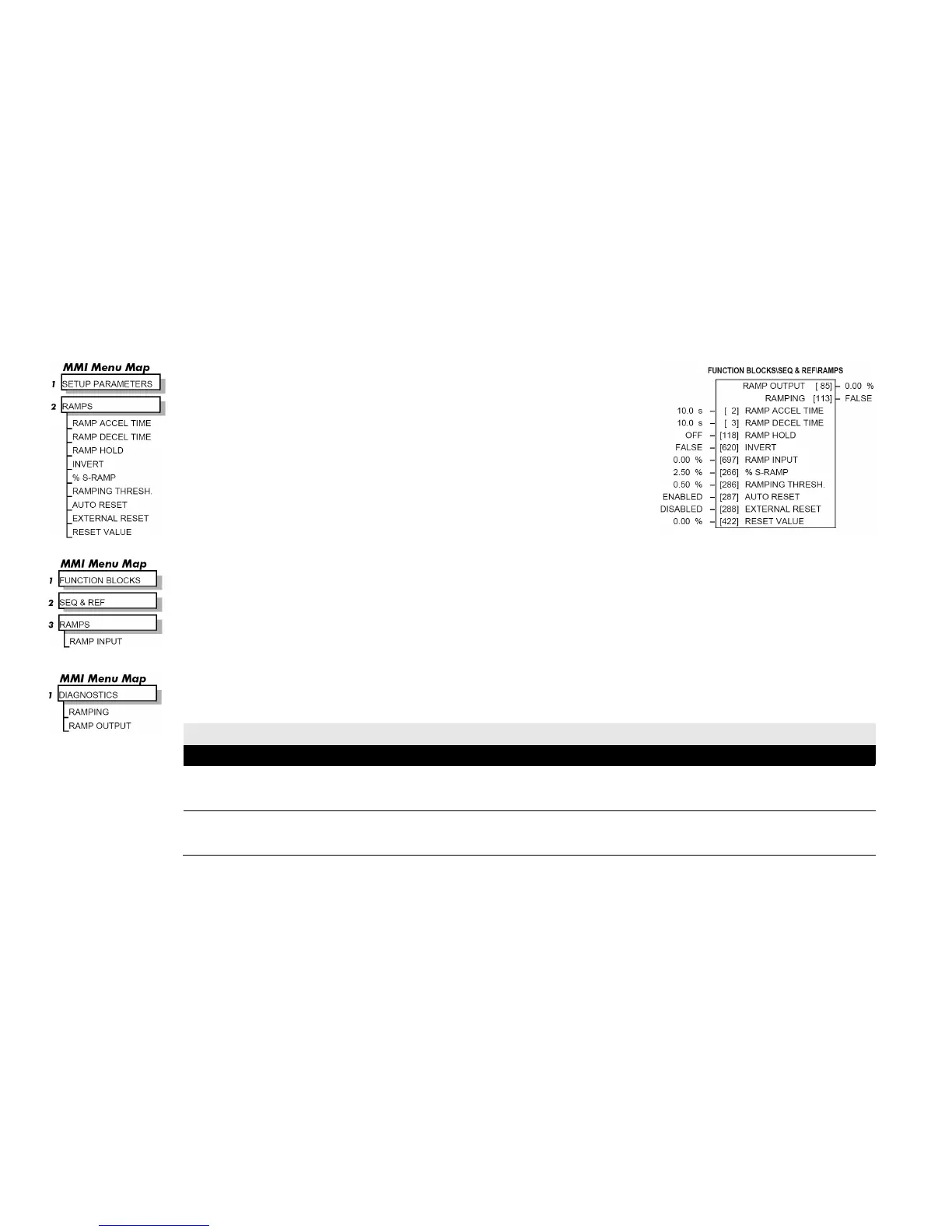
RAMPS
The RAMPS parameters set the shape and duration of the ramp used for starting and
changing speeds.
NOTE The STOP RATES function block contains a separate deceleration rate for
controlled stopping of the drive.
By default the inputs are ANIN 3 (A4) for a ramped speed input, and DIGIN 2 (C7) to switch
RAMP HOLD. The input signal to the block is clamped by MIN SPEED, which sets the minimum
ramp input speed when the drive is enabled. The default output connection is to SPEED LOOP::
SETPOINT 3.
RAMP INPUT is internally routed to the JOG/SLACK function block to be modified as determined
by the JOG inputs. The RAMPS block then shapes the signal to produce the RAMP OUTPUT
signal.
The RAMPING output becomes TRUE when the absolute value of the difference between RAMP OUTPUT and the JOG/SLACK function block
output exceeds RAMPING THRESH.
RAMP ACCEL TIME and RAMP DECEL TIME set the acceleration and deceleration times taken for input changes. % S-RAMP adds a "S" shaped
section to the linear ramp. When set to 0.00%, the ramp will be linear. As the percentage is increased, 350% of the S-RAMP time is added to the linear
ramp creating more gradual starting and stopping. The formula for the actual ramp time is shown below. Ramp time is the value of parameters RAMP
ACCEL TIME or RAMP DECEL TIME.
Actual Ramp Time = RAMP TIME x (3.5 x % S-RAMP/100 + 1)
RAMP HOLD stops the ramp from changing. When DIGIN 2 (C7) is ON, the ramp stays at the last ramp value.
The reset signal can have two sources, a RUN signal or an external reset signal. When AUTO RESET is ENABLED, the ramp resets whenever a Run
signal is given at terminal C3. Connecting a digital input to EXTERNAL RESET allows an external source to reset the ramp.
RAMPS
RAMP ACCEL TIME 2 0.1 to 600.0 s
The acceleration time for 100% change.
RAMP DECEL TIME 3 0.1 to 600.0 s
The deceleration time for 100% change.

 Loading...


