EasyManuals Logo

Parker 590+ series User Manual

Parker 590+ series
545 pages
To Next Page IconTo Next Page
To Previous Page IconTo Previous Page
Page #25 background imageLoading...
Page #25 background image
Product Overview 2-5
DC590+ Series DC Digital Drive
On the Frame 5,
both the Master and Slave drives must be individually
earthed
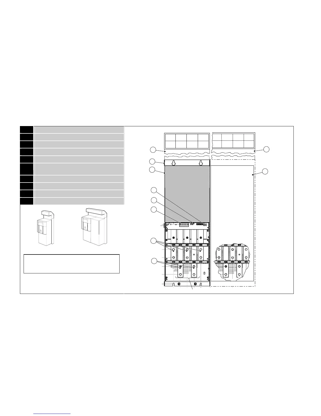
590+ Controller (Frames 4 & 5)
1 Main drive assembly
2 Standard door assembly
3 Motor field terminals
4 Busbars - main power input
5 Busbars - main power output
6 Auxiliary supply, contactor and motor thermistor
terminals
7 Frame 4 External vent (where fitted)
8 Contactor Control Select
9 Frame 5 External vent (where fitted)
10 Terminal Cover (Frame 5)
Frame 4
Frame 5
Assembly
Door
1
2
L1
L2
L3
A+
A-
6
4
5
3
field & auxiliary
connections
via grommet
Product Code 590PD/....
8
9
7
L1
L2
L3
A-
A-
When Frame 5, both terminals are for A+ connections
10
Frame 4
Frame 5

Table of Contents

Questions and Answers:

Question and Answer IconNeed help?

Do you have a question about the Parker 590+ series and is the answer not in the manual?

Parker 590+ series Specifications

General IconGeneral
Control ModeSpeed, Torque, Position
Operating Temperature0°C to 40°C
AltitudeUp to 1000 m without derating
Speed Regulation0.01% of base speed
Communication OptionsEthernet, Profibus, CANbus, Modbus, DeviceNet
Feedback OptionsTachometer, Encoder
Protection RatingIP20
Storage Temperature-25°C to 55°C
Relative Humidity5% to 95% (non-condensing)

Related product manuals