Programming D-117
DC590+ Series DC Digital Drive
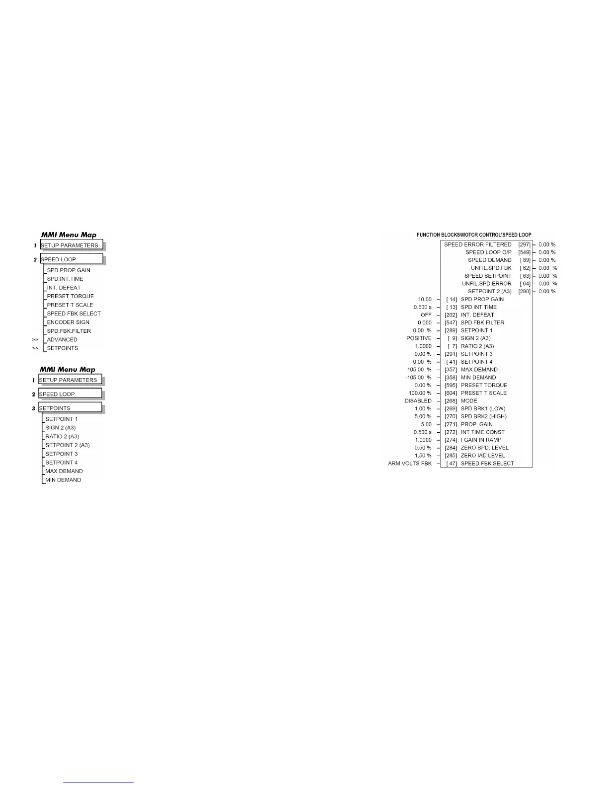
SPEED LOOP
Use this block to tune the speed loop PI to produce a current demand.
This function block has five main functions:
1. Combining the 4 speed setpoints into a single speed setpoint.
Note that the speed demand is created from the combined speed setpoints and
modified by any prevailing stop condition according to the STOP RATES
function block settings.
2. Selection of the speed feedback method.
ZERO SPD OFFSET from the CALIBRATION function block is applied to
the selected speed feedback to null out any remaining feedback at zero actual
speed.
3. Implementation of the PI speed controller.
SPEED DEMAND is summed algebraically with SPEED FEEDBACK to
produce SPEED ERROR. When the drive is enabled, SPEED ERROR is
controlled by the PI loop. The resulting current demand signal is routed to the
CURRENT LOOP function block and to the ADVANCED::ZERO SPD.
QUENCH sub-menu.
The PI output is accessible via Tag No. 356, TOTAL I DMD. This point is
before the I Limit clamps and the summing of the additional current demand.
(This tag is not visible on the MMI).
4. Speed controller gain and integral time constant profiling with speed.
The gains change when the motor speed feedback reaches the thresholds set
by SPD BRK 1 (LOW) and SPD BRK 2 (HIGH).
• At or below SPD BRK 1 (LOW), the speed loop uses the PROP. GAIN and INT. TIME CONST. values as its PI loop gains.
• Between SPD BRK 1 (LOW) and SPD BRK 2 (HIGH), profiling occurs and the speed loop gains are determined by another parameter
value (according to the selection of the MODE parameter).
• Above SPD BRK 2 (HIGH), the SPD. PROP. GAIN and SPD. INT. TIME settings are used.
MODE selects the parameter for profiling the speed loop PI gains when the motor speed is between the two speed breakpoints.

 Loading...


