EasyManuals Logo

Parker 590+ series User Manual

Parker 590+ series
545 pages
To Next Page IconTo Next Page
To Previous Page IconTo Previous Page
Page #41 background imageLoading...
Page #41 background image
Installing the Drive 3-7
DC590+ Series DC Digital Drive
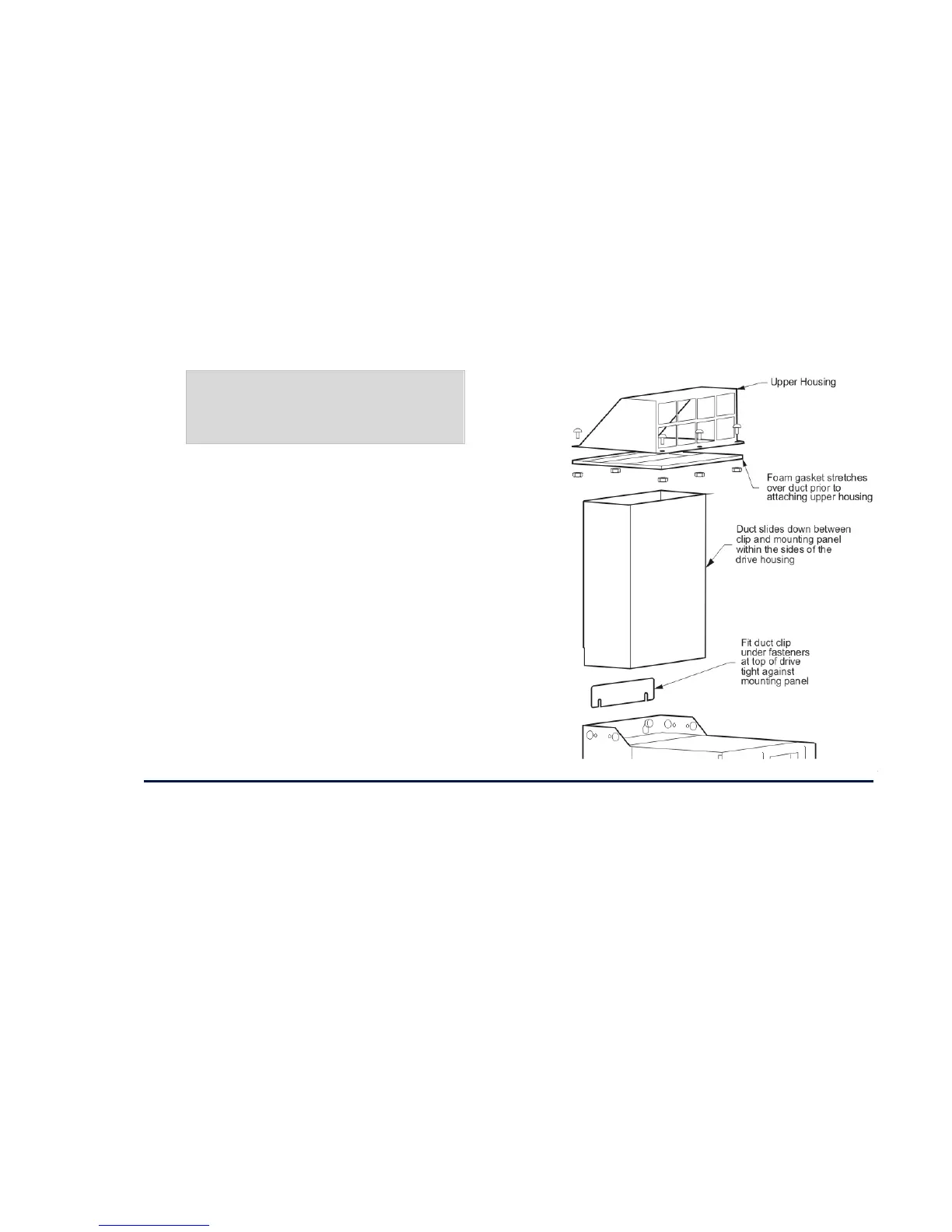
Installing the External Vent Kit (Frames 4 & 5)
Parker SSD Part Drives Numbers:
Frame 4 : LA466717U001
Frame 5 : LA466717U002
Refer also to page
32H3-80 and page 33H3-85.
Figure 3- 3 Frames 4 & 5 External Vent Kit
AC Line Choke
We recommend that you always use the specified ac line choke with the Drive
to provide a known supply impedance for effective operation of the thyristor transient suppression circuits. At least 1% line impedance should be
provided in the supply side of the drive.
Refer to Appendix E: “Technical Specifications” - AC Line Choke for selection details.

Table of Contents

Questions and Answers:

Question and Answer IconNeed help?

Do you have a question about the Parker 590+ series and is the answer not in the manual?

Parker 590+ series Specifications

General IconGeneral
Control ModeSpeed, Torque, Position
Operating Temperature0°C to 40°C
AltitudeUp to 1000 m without derating
Speed Regulation0.01% of base speed
Communication OptionsEthernet, Profibus, CANbus, Modbus, DeviceNet
Feedback OptionsTachometer, Encoder
Protection RatingIP20
Storage Temperature-25°C to 55°C
Relative Humidity5% to 95% (non-condensing)

Related product manuals