A-48 Fieldbuses
AC30 series Variable Speed Inverter
Acyclic Access of Inverter Parameters
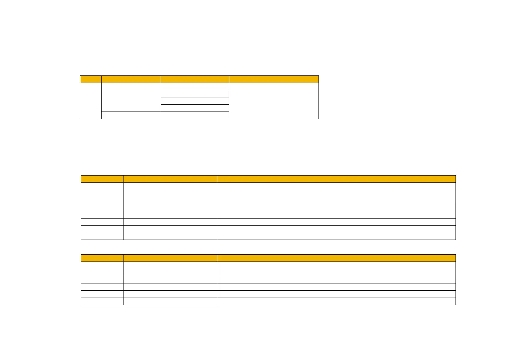
Acyclic access of inverter parameters by the PLC is possible using read and write record requests in the user specific index range (0 to 0x7FFF).
Access is achieved via any plugged slot/subslot, however use of the DAP slot is recommended as this is always plugged regardless of the
application. There is a direct relationship between the Parameter Number (PNO) and the record Index. This is shown in the table below.
The current value of the parameter plugged into a slot/subslot may also be read using index 0. Writing to a parameter via index 0 is not possible.
Function Blocks
The functions blocks RDREC and WRREC are used for read requests and write requests respectively. The inputs / outputs to the function blocks
of interest are:
Other plugged slot/subslot
Identifier of a slot/subslot
For a Step 7 PLC the diagnostic address found in Slot 0 and Subslot 1 would be used.
For a CoDeSys PLC the ID field of the PROFINET slave would be used.
To access the inverter parameters use the PNO for the index
RDREC only - maximum length of the data to be read. See Read Record section
WRREC only - length of the data to be written. See Write Record section.
Data will be written to this area following a read request.
Data will be read from this area for a write request.
New data received and is valid
See Record Error Codes section
See Record Error Codes section

 Loading...


