EasyManuals Logo

Parker AC30 series User Manual

Parker AC30 series
462 pages
To Next Page IconTo Next Page
To Previous Page IconTo Previous Page
Page #24 background imageLoading...
Page #24 background image
4-2 The Graphical Keypad
AC30 series Variable Speed Inverter
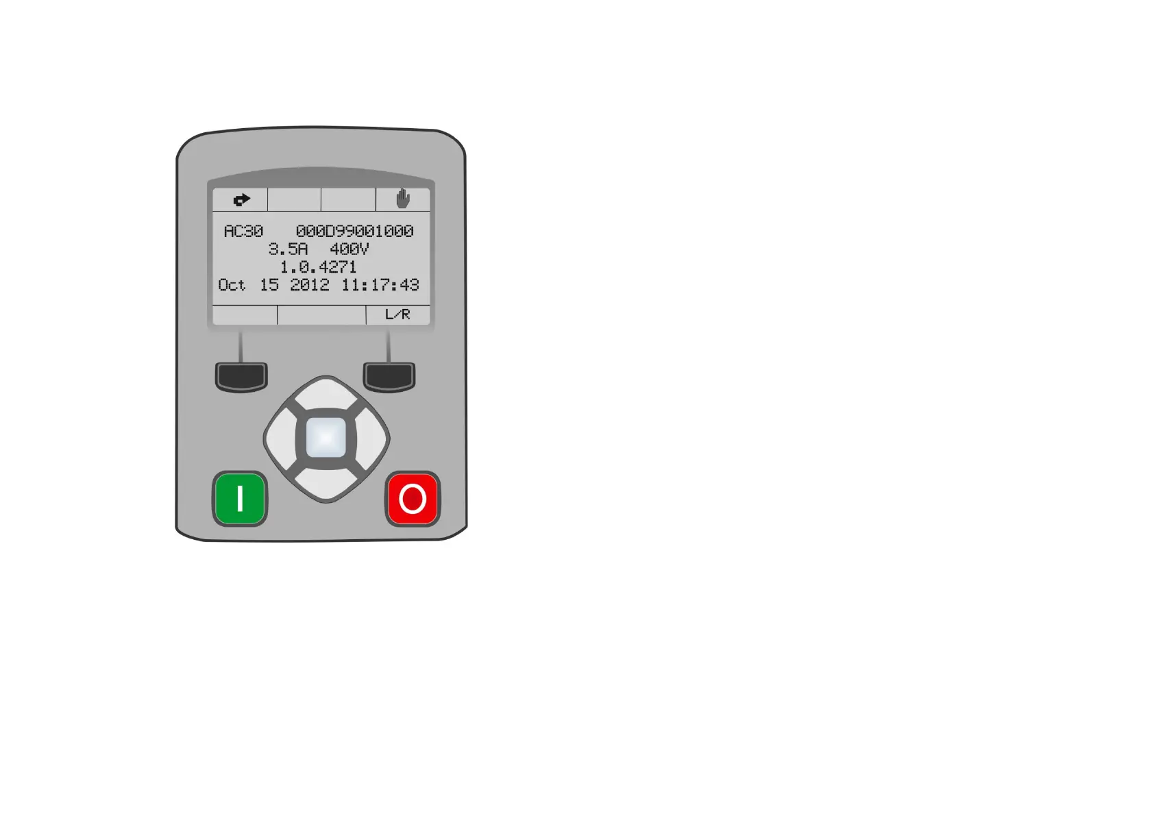
Overview
The top line of the display is used to show the inverter status
The central region of the display shows the selected parameters or navigation menu
The bottom line of the display indicates the action associated with the soft keys
The actions of the soft keys are context dependent
The cen
tral navigation and editing keys are referred to as UP, DOWN, LEFT, RIGHT and
OK
The Run, (green), and Stop, (red), keys are used to start and stop the motor when the
inverter is in local control mode.

Table of Contents

Other manuals for Parker AC30 series

Questions and Answers:

Question and Answer IconNeed help?

Do you have a question about the Parker AC30 series and is the answer not in the manual?

Parker AC30 series Specifications

General IconGeneral
Control ModesClosed-loop vector
FeedbackEncoder
Operating Temperature0 to 40°C (32 to 104°F) standard, -20 to 50°C (-4 to 122°F) with derating
ProtectionOvercurrent, Overvoltage, Undervoltage
CommunicationRS485

Related product manuals