EasyManuals Logo

Parker AC30 series User Manual

Parker AC30 series
462 pages
To Next Page IconTo Next Page
To Previous Page IconTo Previous Page
Page #159 background imageLoading...
Page #159 background image
Fieldbuses A-37
AC30 series Variable Speed Inverter
Example PLC Configurations
The examples in this section uses the default parameter mapping of the inverter:
Example Using a SIMATIC S7-300 PLC and SIMATIC Manager
1. Create a project
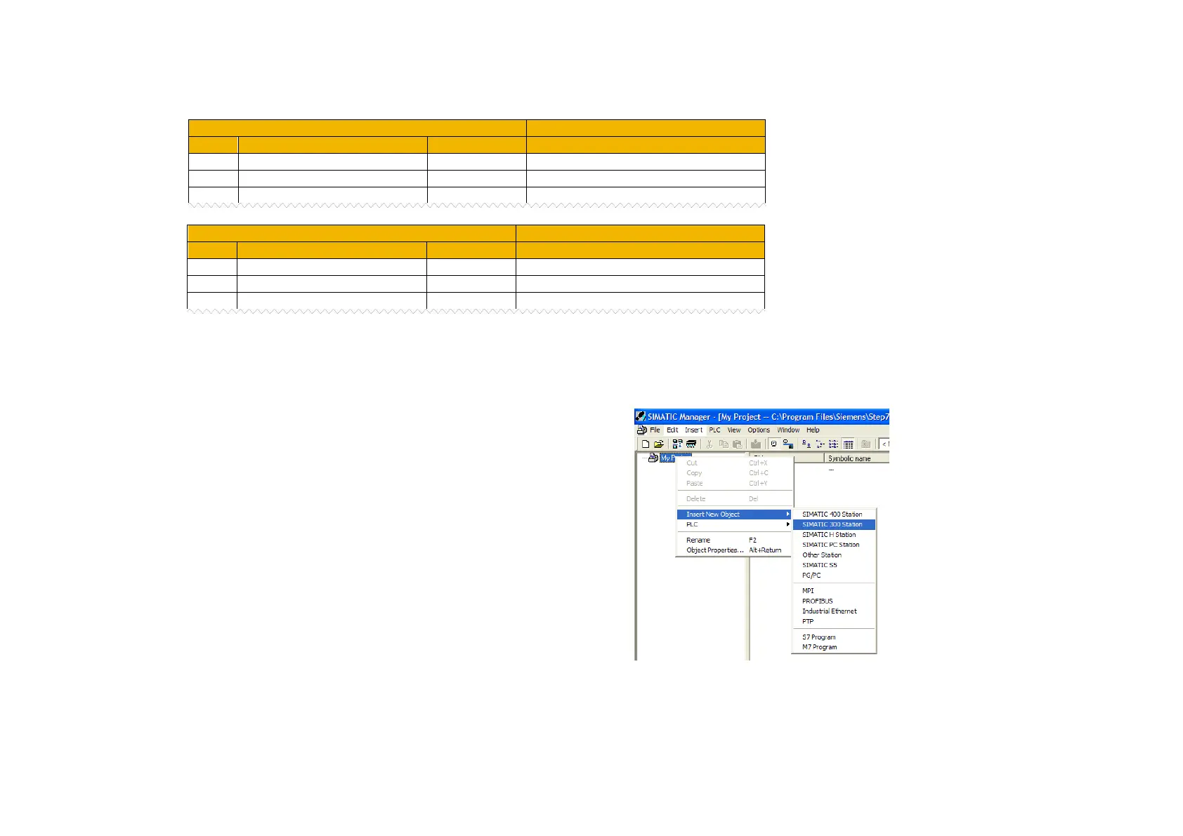
Start SIMATIC Manager and create a new project. Right-click on the
project name at the top level and from Insert New Object select
SIMATIC 300 Station.
AC30 Input Mapping Table
PLC Outputs
AC30 Parameter
Data Type
Plugged Modules
000
0627 Comms Control Word
WORD
Output Unsigned16
001
0681 Comms Reference
REAL
Output Real
002
0000
AC30 Output Mapping Table
PLC Inputs
AC30 Parameter
Data Type
Plugged Modules
000
0661 Status Word
WORD
Input Unsigned16
001
0395 Actual Speed Percent
REAL
Input Real
002
0000

Table of Contents

Other manuals for Parker AC30 series

Questions and Answers:

Question and Answer IconNeed help?

Do you have a question about the Parker AC30 series and is the answer not in the manual?

Parker AC30 series Specifications

General IconGeneral
Control ModesClosed-loop vector
FeedbackEncoder
Operating Temperature0 to 40°C (32 to 104°F) standard, -20 to 50°C (-4 to 122°F) with derating
ProtectionOvercurrent, Overvoltage, Undervoltage
CommunicationRS485

Related product manuals