The Graphical Keypad 4-5
AC30 series Variable Speed Inverter
The Display
The display is divided into three areas:
1. Top line: shows a summary of the inverter status.
2. Centre region: is the main work area where menus and parameters are displayed.
3. Bottom line: is used to indicate the action associated with the soft keys.
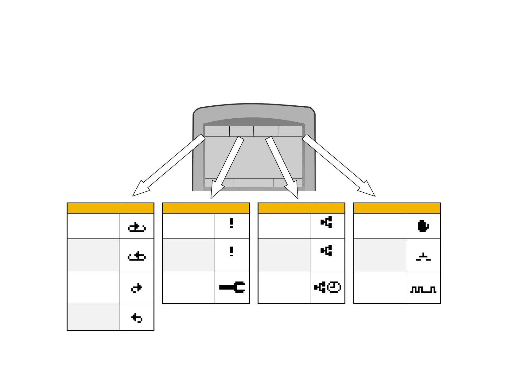
Top Line - Inverter Status Summary
The top line of the display shows a summary of the inverter status. This is divided into four regions. Each region is dedicated to a particular status
indication, as shown.
Running
+ve direction
Inverter Tripped
(flashing)
IP address
missing
(flashing)
Local:
Start / Stop
Running
-ve direction
Warning
(solid)
IP address
configured
(solid)
Remote:
Start / Stop
from control
terminals
Stopped
(ready to run in
+ve direction)
Maintenance
required
IP Address
configured, PTP
clock
synchronised
Comms:
Start / Stop
from comms
Stopped
(ready to run in
-ve direction)

 Loading...


