EasyManuals Logo

Parker AC30 series User Manual

Parker AC30 series
462 pages
To Next Page IconTo Next Page
To Previous Page IconTo Previous Page
Page #26 background imageLoading...
Page #26 background image
4-4 The Graphical Keypad
AC30 series Variable Speed Inverter
LED Status Indication
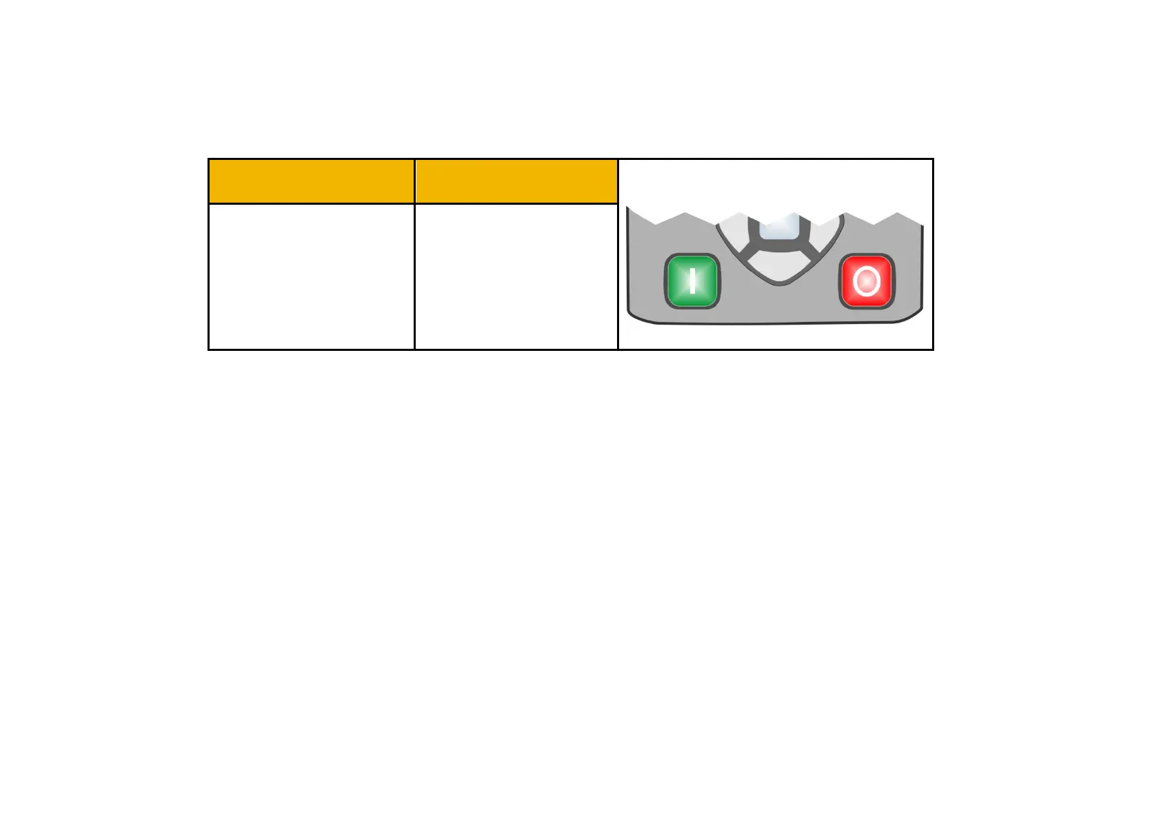
The GKP has two LED illuminated pushbuttons the green ‘Run’ key and the red ‘Stop’ key.
The status of each of these LED illuminated pushbuttons indicates the real time operation of the inverter:
LED Status
Inverter Status:
Run Key
Stop Key
OFF ON STOPPED
ON OFF RUNNING
OFF FLASHING STOPPING
FLASHING OFF AUTO RESTART PENDING
FLASHING (IN SYNC)
NOT IN AN OPERATIONAL
STATE
FLASHING (ALTERNATING) FAULT STATE
Note: The LED operation can be over-ridden by the application.

Table of Contents

Other manuals for Parker AC30 series

Questions and Answers:

Question and Answer IconNeed help?

Do you have a question about the Parker AC30 series and is the answer not in the manual?

Parker AC30 series Specifications

General IconGeneral
Control ModesClosed-loop vector
FeedbackEncoder
Operating Temperature0 to 40°C (32 to 104°F) standard, -20 to 50°C (-4 to 122°F) with derating
ProtectionOvercurrent, Overvoltage, Undervoltage
CommunicationRS485

Related product manuals