Sequencing Logic B-5
AC30 series Variable Speed Inverter
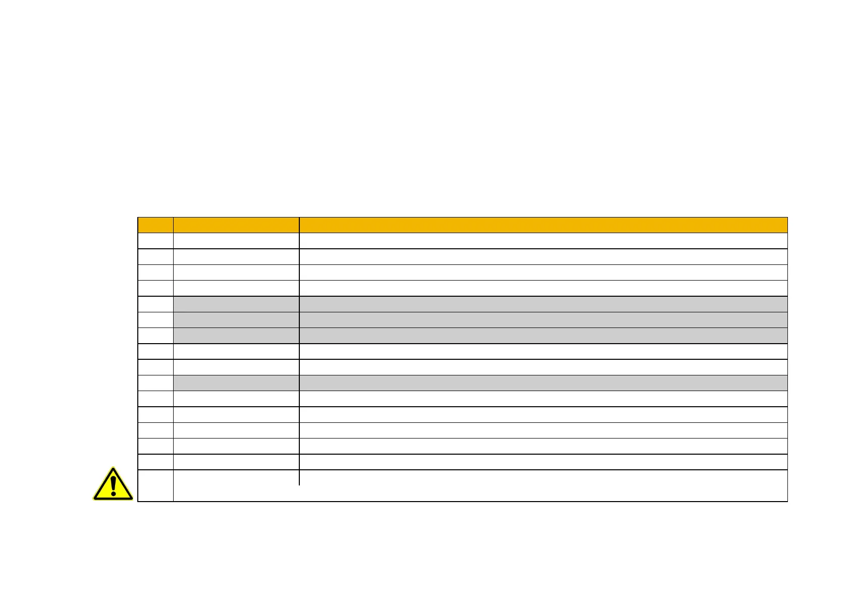
Control Word
The commands that request a change in sequencer state are received via the Control Word. The current value is given by 0644 Control Word.
This is a read-only parameter which is updated from a source depending on the selected sequencing control channel. The sources available are
COMMS, APP and LOCAL.
If COMMS is selected, the value will be taken from 0627 Comms Control Word. This will normally be written to over either the Fieldbus interface
or built-in Ethernet Modbus TCP. The Not Quickstop, Enable Voltage and Switch On bits are ANDed with 0610 App Control Word. The External
Fault is ORed with the 0610 App Control Word.
If APP is selected, the value will be taken from 0610 App Control Word. This will normally be written to by the loaded application which is
responsible for routing the control signals from Digital Input terminals.
If LOCAL is selected, the value will be written to by the GKP with the Not Quickstop, Enable Voltage, External Fault and Switch On bits from 0610
App Control Word.
OFF3 = 0 to emergency stop
=0 to set ramp output to zero Not implemented, See note below
=0 to hold ramp Not implemented, See note below
=0 to set ramp input to zero
Not implemented, See note below
Reset trips on 0 to 1 transition
1 = External (Application) trip active
unused
1 = Use 0627 Comms Control Word as the Control Word source for sequencing
1 = Use 0681 Comms Reference as the Reference source
1 = Run using 0501 Jog Setpoint when Enable Operation = 1
1 = Run in reverse direction when Enable Operation = 1
1 = Allow SWITCH ON DISABLED to READY TO SWITCH ON transition regardless of bit 0 (Switch On)
15
1 = Rising-edge of Enable Operation required for SWITCHED ON to OPERATION ENABLED transition
Setting “Event Triggered OP” to 0 could cause the motor to start unexpectedly.
Note – bits 4, 5, 6 must be set (= 1) to allow the ramp control feature to be added in the future.

 Loading...


