Sequencing Logic B-3
AC30 series Variable Speed Inverter
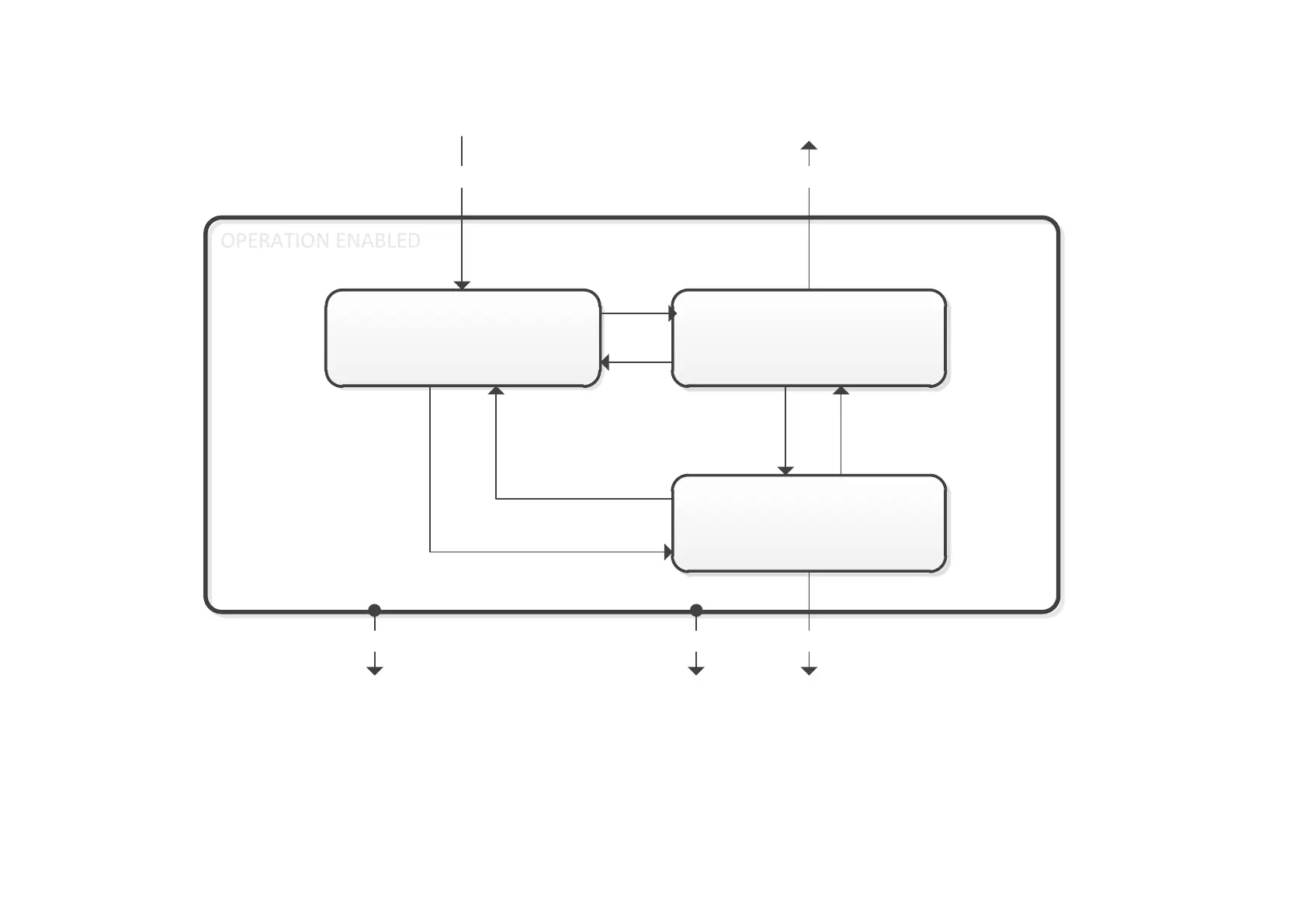
The OPERATION ENABLED state is the normal operation state of the Drive. In this state the Reference Ramp is active, generating a Speed
Demand. Sub-states and allowed transitions are shown below. Note – the RUNNING sub-state also includes JOGGING.
OPERATION ENABLED
OPERATION ENABLED
RUNNING
STOPPING
(DISABLE OPERATION)
SHUTTING DOWN
(SWITCH OFF)
4
89 11
5
State Transitions
State transitions are caused by internal events in the Drive or external commands via the Control Word. The transition numbers below relate to
those on the Sequence Diagram.
Transition 0: No Power to NOT READY TO SWITCH ON
Power has been applied to the control electronics of the drive.

 Loading...


